Category Archive Manuals

Byvelma

tc-900e 2hp manual

This manual provides essential guidance for installing‚ configuring‚ and operating the TC-900E 2HP digital controller‚ ensuring optimal performance and energy efficiency in refrigeration systems.

1.1 Overview of the TC-900E 2HP Controller

The TC-900E 2HP is a digital controller designed for refrigeration and defrost systems‚ offering intelligent defrosting and energy-saving features. It automates defrost processes based on facility needs‚ ensuring efficient operation. With three relays for compressors‚ defrost‚ and fans‚ it supports temperature sensors and digital inputs for precise control. Ideal for freezers‚ cold storage‚ and display cases‚ it combines advanced functionality with user-friendly interfaces‚ making it a versatile solution for modern refrigeration requirements.

1.2 Importance of the Manual for Users

The manual is crucial for understanding the TC-900E 2HP’s features‚ installation‚ and operation. It provides detailed setup instructions‚ feature explanations‚ and troubleshooting guidance‚ ensuring optimal performance and energy savings. Users can avoid costly errors by following the manual’s guidelines‚ making it essential for safe and effective system operation. The manual also helps users customize settings for specific applications‚ maximizing efficiency and extending equipment lifespan. Adhering to the manual ensures reliable‚ economical‚ and professional management of refrigeration systems.

Key Features of the TC-900E 2HP Controller

The TC-900E 2HP offers advanced digital control for refrigeration and defrost systems‚ intelligent defrosting‚ energy-saving modes‚ and user-friendly interfaces‚ ensuring efficient and reliable operation.

2.1 Digital Controller for Refrigeration and Defrost Systems

The TC-900E 2HP is a digital controller designed to manage refrigeration and defrost systems efficiently. It automates temperature control and defrost cycles‚ ensuring precise operation. The controller supports two defrost modes: temperature-based and time-based‚ allowing flexibility for different applications. With advanced sensors and relays‚ it optimizes performance while minimizing energy consumption. This makes it ideal for use in freezers‚ cold storage‚ and display cases‚ ensuring consistent refrigeration and reduced maintenance needs. Its intuitive interface simplifies setup and monitoring‚ making it a reliable choice for various commercial refrigeration setups.

2.2 Intelligent Defrosting Capabilities

The TC-900E 2HP features intelligent defrosting‚ automating the process based on system needs. It offers two modes: temperature-triggered and time-based defrost‚ ensuring efficient operation. This adaptive defrosting prevents excessive icing‚ maintaining optimal performance while reducing energy consumption. The controller’s smart algorithms adjust defrost cycles‚ minimizing unnecessary activations and prolonging system lifespan. This intelligent feature optimizes energy use‚ reduces wear on components‚ and ensures consistent refrigeration performance‚ making it ideal for commercial and industrial applications requiring precise temperature control.

2.3 Energy-Saving Functionality

The TC-900E 2HP incorporates advanced energy-saving features‚ optimizing refrigeration processes to minimize power consumption. It utilizes adaptive algorithms to reduce unnecessary compressor cycles and defrost operations. The controller’s economy set point adjusts energy use during low-demand periods‚ while normal set points ensure efficient cooling. These features collectively reduce operational costs‚ lower environmental impact‚ and extend system lifespan‚ making the TC-900E 2HP a cost-effective solution for modern refrigeration needs.

Technical Specifications of the TC-900E 2HP

The TC-900E 2HP operates within a -50°C to 105°C temperature range‚ featuring 3 relays‚ 2 temperature sensors‚ and 2 digital inputs‚ supporting real-time clock and data logging.

3.1 Temperature Range and Sensitivity

The TC-900E 2HP controller operates effectively within a temperature range of -50°C to 105°C‚ ensuring precise control for various refrigeration applications. Its high sensitivity allows accurate temperature regulation‚ maintaining optimal conditions for frozen foods and perishables. This wide range makes it suitable for both low-temperature freezers and high-ambient environments‚ providing reliable performance across diverse settings. The controller’s ability to maintain consistent temperatures ensures energy efficiency and prevents unnecessary cycling‚ enhancing overall system reliability and longevity.

3.2 Relay Outputs (Compressor‚ Defrost‚ Fan)

The TC-900E 2HP controller features three dedicated relay outputs for precise control of the compressor‚ defrost‚ and fan systems. The compressor relay supports up to 2HP‚ ensuring robust performance for refrigeration cycles. The defrost relay has a 10A capacity‚ enabling efficient defrosting operations. The fan relay manages auxiliary systems‚ optimizing airflow and temperature distribution. These outputs are designed to automate and regulate the system seamlessly‚ ensuring energy efficiency and reliable operation across various refrigeration applications.

3.3 Sensor and Input/Output Configurations

The TC-900E 2HP controller is equipped with two temperature sensors for precise monitoring and control. It features two digital inputs for customization and integration with external systems. The controller supports a real-time clock and data logging capabilities‚ enabling accurate temperature tracking. Additionally‚ it includes a light intensity sensor for ambient light detection‚ enhancing automation in display cases. These configurations ensure seamless operation‚ adaptability‚ and advanced monitoring for refrigeration systems‚ making it ideal for various applications.

Installation and Setup Guidance

Follow step-by-step installation instructions and configure parameters for optimal performance. Troubleshoot common issues to ensure proper setup and operation of the TC-900E 2HP controller.

4.1 Step-by-Step Installation Instructions

Mount the controller securely‚ ensuring proper ventilation. Connect power supply‚ temperature sensors‚ and relay outputs carefully. Configure defrost and fan settings according to application needs. Enable real-time clock and light intensity sensor if required. Test all functions before finalizing setup. Refer to the manual for detailed diagrams and troubleshooting guidance to ensure correct installation and optimal performance. Follow safety precautions to avoid damage or electrical hazards.

4.2 Configuration Parameters for Optimal Performance

Set temperature range between -50°C to 105°C for precise control. Configure defrost modes (temperature or time-based) to suit application needs. Adjust relay outputs for compressor‚ defrost‚ and fan operations. Enable energy-saving modes and economy set points. Configure digital inputs for external sensors or switches. Set real-time clock and light intensity sensor thresholds for automated adjustments. Adjust defrost duration and intervals to prevent excessive energy use. Ensure all settings align with the specific requirements of your refrigeration system for efficient and reliable operation.

4.3 Troubleshooting Common Installation Issues

Check wiring connections for loose or incorrect terminals. Verify sensor calibration and ensure proper installation; If relays fail to activate‚ review configuration settings. Address error codes by referencing the manual. Ensure power supply matches requirements. Reset the controller if it locks up. Verify defrost and compressor settings align with system needs. Consult the troubleshooting section for specific error resolutions. Contact technical support if issues persist after basic checks.

Operating the TC-900E 2HP Controller

Operate the TC-900E 2HP controller effortlessly with intuitive controls‚ real-time monitoring‚ and precise temperature adjustments‚ ensuring efficient management of refrigeration and defrost cycles.

5.1 Quick Access Keys and Functions

The TC-900E 2HP controller features quick access keys that simplify operation. When the display shows temperature‚ specific keys act as shortcuts for functions like defrost initiation and set point adjustments. The scroll key navigates menus‚ while others directly access defrost modes or economy settings. Real-time monitoring and data logging enhance operational efficiency‚ ensuring precise temperature control and energy savings. These intuitive controls enable users to manage refrigeration and defrost cycles effortlessly‚ optimizing performance and reducing downtime.

5.2 Defrost Initiation Modes (Temperature or Time)

The TC-900E 2HP controller offers two defrost initiation modes: temperature-based and time-based. Temperature mode triggers defrost when a set temperature is reached‚ while time mode defrosts at predefined intervals. This dual functionality ensures efficient frost removal without unnecessary energy consumption. Manual defrost is also available for immediate intervention. These modes adapt to facility needs‚ maintaining optimal performance and preventing excessive ice buildup in refrigeration systems‚ thus preserving product quality and system longevity.

5.3 Normal and Economy Set Points

The TC-900E 2HP controller features Normal and Economy set points‚ allowing users to balance energy consumption and temperature maintenance. Normal mode prioritizes precise temperature control‚ while Economy mode reduces energy use during off-peak periods. These set points are triggered automatically based on time settings‚ ensuring optimal performance without manual intervention. This dual-mode functionality enables efficient operation‚ adapting to varying demands while maintaining product quality and minimizing energy costs in refrigeration systems.

Maintenance and Care

Regular maintenance is essential for optimal performance and longevity of the TC-900E 2HP controller. This section covers routine tasks‚ software updates‚ and environmental considerations to ensure reliability.

6.1 Regular Maintenance Tasks

Regular maintenance ensures the TC-900E 2HP controller operates efficiently. Clean the unit‚ check sensors‚ and verify relay connections. Update software periodically and inspect for wear. Ensure proper installation and environmental conditions are met to prevent damage. Schedule these tasks to maintain performance and extend lifespan. Important: Follow guidelines to avoid system downtime and ensure reliability in refrigeration systems. Regular checks prevent issues before they arise‚ safeguarding your equipment and operations.

6.2 Software Updates and Firmware

6.3 Cleaning and Environmental Considerations

Advanced Features and Benefits

  • Data logging and real-time monitoring enhance performance tracking.
  • Light intensity sensor integration optimizes defrost and temperature control.
  • Energy-saving modes reduce operational costs significantly.

7.1 Data Logging and Real-Time Monitoring

The TC-900E 2HP features advanced data logging‚ capturing temperature‚ defrost cycles‚ and system performance. Real-time monitoring allows users to track current conditions‚ ensuring precise control and timely interventions. Historical data can be reviewed to optimize settings‚ identify trends‚ and maintain consistent refrigeration performance. This functionality supports efficient system management and compliance with operational standards‚ making it invaluable for commercial and industrial applications.

7.2 Light Intensity Sensor Integration

The TC-900E 2HP integrates a light intensity sensor‚ enabling automatic adjustments based on ambient light levels. This feature is particularly useful in display cases‚ where lighting fluctuations can impact temperature control. The sensor ensures consistent performance by adapting defrost and cooling cycles to match environmental conditions. This integration enhances energy efficiency and maintains optimal temperatures‚ making it ideal for applications like retail display freezers and cold storage units.

7;3 Energy Efficiency and Cost Savings

The TC-900E 2HP is designed with energy-saving features‚ optimizing compressor and defrost cycles to reduce power consumption. Intelligent defrosting minimizes unnecessary cycles‚ while adaptive temperature control ensures efficient operation. This reduces energy bills and extends equipment lifespan‚ making it a cost-effective solution for commercial refrigeration systems. By automating processes‚ the controller helps users achieve long-term savings and environmental benefits without compromising performance.

Applications of the TC-900E 2HP Controller

The TC-900E 2HP is ideal for freezers‚ cold storage rooms‚ display cases‚ and other refrigeration applications‚ ensuring precise temperature control and efficient operation in various commercial settings.

8.1 Ideal Use Cases (Freezers‚ Cold Storage‚ Display Cases)

The TC-900E 2HP controller is perfect for managing temperature in freezers‚ cold storage facilities‚ and display cases. Its digital precision ensures optimal conditions‚ preventing overheating or freezing. With intelligent defrosting and energy-saving features‚ it’s ideal for supermarkets‚ warehouses‚ and retail environments requiring consistent refrigeration. The controller’s durability and adaptability make it a reliable choice for maintaining product quality and reducing operational costs in demanding commercial settings.

Accessing the TC-900E 2HP Manual

The TC-900E 2HP manual can be downloaded as a PDF or viewed online‚ offering detailed guidance for installation‚ operation‚ and troubleshooting with easy navigation.

9.1 Downloading the Manual in PDF Format

The TC-900E 2HP manual is available for free download in PDF format from the official website. Users can save it to their desktop or laptop for offline access. The PDF file provides detailed information on installation‚ operation‚ and troubleshooting. It also includes quick access keys and configuration parameters. Simply right-click the download link and select “Save Target As” to store the manual. This ensures easy access to guidance anytime‚ even without internet connectivity.

9.2 Online Viewing and Navigation

The TC-900E 2HP manual can be viewed online directly in your web browser‚ offering convenient access to its contents without downloading. The manual features a scroll bar for easy navigation‚ allowing users to scroll through pages seamlessly. Each section is clearly indexed‚ making it simple to locate specific information. The online version includes detailed instructions‚ diagrams‚ and quick access keys for efficient operation. This format ensures users can quickly find the information they need‚ even without prior technical expertise.

Byvelma

arctic king freezer manual troubleshooting

The Arctic King Freezer manual provides essential troubleshooting guidance, empowering users to identify and resolve common issues like power failures or temperature malfunctions effectively to ensure optimal performance.

Importance of the User Manual

The user manual for the Arctic King Freezer is a valuable resource that provides essential information for proper operation, maintenance, and troubleshooting. It contains detailed instructions, diagrams, and safety precautions to ensure the freezer functions optimally. By referring to the manual, users can identify common issues early, such as power supply problems or temperature malfunctions, and address them effectively. The manual also offers step-by-step guides for resolving faults, which can prevent further damage and reduce repair costs. Additionally, it serves as a reference for understanding the freezer’s features and settings, helping users customize performance to their needs. Regularly reviewing the manual can enhance safety, efficiency, and overall satisfaction with the appliance.

Common Issues Addressed in the Manual

The Arctic King Freezer manual addresses a variety of common issues, including power supply problems, cooling failures, and frost buildup. It provides solutions for temperature control malfunctions and strange noises, ensuring users can troubleshoot effectively. The manual also covers defrosting techniques and thermostat adjustments, helping to maintain optimal performance. By outlining these issues and their fixes, the manual empowers users to resolve problems independently, minimizing the need for professional assistance. It ensures a smoother operation and extends the lifespan of the freezer, making it a crucial resource for all users.

Understanding Common Arctic King Freezer Problems

Common issues include power supply disruptions, cooling failures, excessive frost buildup, and temperature control malfunctions. These problems are addressed with practical solutions to ensure optimal freezer performance.

Power Supply Issues

Power supply problems are among the most common issues with Arctic King freezers. If the freezer does not turn on, check the power cord and outlet. Ensure the unit is properly plugged in and that no fuses have blown or circuit breakers tripped. A dedicated circuit for the freezer is recommended to avoid overloading. If the freezer suddenly stops working, it may indicate a power supply interruption. Always unplug the freezer before inspecting or repairing internal components. Consult a licensed electrician if you suspect electrical issues. Proper power supply is crucial for the freezer’s operation and longevity, so addressing these problems promptly is essential for maintaining optimal performance and preventing further damage. Regular checks can help prevent unexpected disruptions in the freezer’s functionality.

Cooling Failures

Cooling failures in Arctic King freezers can lead to rising temperatures, compromising stored food. If the freezer isn’t cooling, check the thermostat settings. Ensure it’s set correctly and not too high. Next, inspect the door seals for tightness, as gaps can let warm air enter. Blockages in air vents or evaporator coils can also hinder cooling. Clean the coils and ensure proper air circulation around the unit. Additionally, check for any ice buildup, which may require defrosting. If issues persist, professional assistance may be needed to diagnose internal components like the compressor or refrigerant levels. Addressing cooling failures promptly prevents food spoilage and extends the freezer’s lifespan. Regular maintenance, such as cleaning and inspecting seals, can help avoid these issues. Always ensure the freezer is on a level surface to maintain even cooling distribution.

Frost Buildup and Defrosting

Frost buildup in Arctic King freezers can impede performance and storage capacity. Excessive ice formation often results from improper door sealing or inconsistent temperature settings. Regular defrosting is essential to maintain efficiency. If frost accumulates, unplug the freezer and allow it to thaw completely. Use a soft scraper or cloth to remove ice, avoiding damage to internal components. After defrosting, ensure the door seals are clean and free of debris to prevent future buildup. Additionally, check the defrost timer and heater for proper function. Some models feature automatic defrost, but manual intervention may still be necessary. Always refer to the user manual for specific defrosting instructions tailored to your model. Proper maintenance helps maintain optimal cooling and prevents energy waste. Regular checks can prevent severe frost accumulation, ensuring your freezer operates smoothly and effectively.

Temperature Control Malfunctions

Temperature control issues in Arctic King freezers can arise from faulty thermostats, sensor malfunctions, or incorrect settings. If the freezer isn’t cooling properly, check the thermostat settings to ensure they’re within the recommended range. Adjust the temperature control dial to a lower setting if necessary. Verify that the freezer is placed away from direct sunlight or heat sources, as this can interfere with temperature regulation. Inspect the control panel for any error codes or malfunctions, as it manages the temperature system. If problems persist, consult the user manual for specific guidance on resetting or calibrating the temperature controls. Addressing these issues promptly ensures consistent cooling performance and prevents food spoilage. Regular checks can help maintain optimal temperature levels and overall freezer efficiency.

Step-by-Step Troubleshooting Guide

This guide offers a structured approach to diagnosing freezer issues, from identifying power problems to resolving temperature control malfunctions, ensuring efficient troubleshooting and optimal performance.

Checking the Power Supply

Start by ensuring the freezer is properly plugged into a functioning electrical outlet. Verify that the power cord is undamaged and securely connected to both the freezer and the wall. If using an extension cord, ensure it is rated for the freezer’s power requirements. Check the circuit breaker or fuse box to confirm that the breaker hasn’t tripped or a fuse hasn’t blown. If the freezer still doesn’t power on, consult the user manual for specific electrical requirements or reset the breaker. A stable power supply is crucial for the freezer’s operation, and addressing these basics can often resolve common issues quickly and effectively.

Inspecting the Thermostat Settings

Check the thermostat settings to ensure it is set correctly for your needs. The Arctic King Freezer thermostat is typically located inside the freezer compartment and may have a dial or digital controls. Verify that the temperature setting is not too high, as this can prevent proper cooling. If the freezer is not cooling, try lowering the temperature setting slightly. Conversely, if it’s too cold, raising the setting can prevent excessive frost buildup. Always refer to the user manual for specific guidance on adjusting the thermostat, as improper settings can lead to inefficient operation or mechanical issues. Regular inspection of the thermostat ensures optimal performance and prevents unnecessary energy consumption.

Addressing Frost Buildup

Frost buildup in your Arctic King Freezer can reduce efficiency and storage space. Regular defrosting is essential to maintain optimal performance. If excessive frost accumulates, check if the automatic defrost function is working properly. If the freezer does not have an automatic defrost feature, manually defrost by turning it off and allowing ice to melt. Ensure the door seals are tight to prevent moisture entry, which contributes to frost. After defrosting, clean the interior and drain excess water. Proper ventilation around the freezer is also crucial to prevent humidity buildup. Refer to the manual for specific defrosting instructions, as improper methods can damage the unit. Regular maintenance helps prevent frost-related issues and keeps your freezer running efficiently.

Resetting the Freezer

Resetting your Arctic King Freezer can often resolve operational issues. Start by unplugging the unit from the power source to ensure safety. Allow it to remain unplugged for at least 30 minutes to reset internal components. After this period, plug it back in and adjust the thermostat to the desired temperature setting. This process can clear minor technical glitches, such as faulty sensors or control panel malfunctions. If the freezer does not restart properly, inspect the power cord and outlet for damage. If issues persist, consult the user manual or contact customer support for further assistance. Resetting is a simple yet effective troubleshooting step to restore functionality without professional intervention.

Advanced Troubleshooting Techniques

Advanced troubleshooting involves diagnosing complex issues like strange noises or control panel malfunctions, often requiring detailed manual guidance to resolve efficiently and restore optimal freezer performance.

Identifying Strange Noises

Strange noises from your Arctic King freezer can indicate underlying issues. Common sounds include clicking, rattling, or humming, which may stem from faulty compressors, loose parts, or uneven leveling. To diagnose, unplug the freezer and inspect internal components like fans or evaporator coils for obstructions. Consult the manual for guidance on identifying specific noises and their causes. Addressing these issues promptly can prevent further damage. If the problem persists, contact professional support for assistance. Regular maintenance, like ensuring proper leveling and cleaning, can also minimize the risk of unusual noises. Always follow safety precautions when troubleshooting to avoid accidents or injuries. By understanding the source of the noise, you can apply the appropriate fix and restore your freezer’s normal operation. Proper care ensures longevity and efficiency.

Diagnosing Control Panel Issues

Control panel issues in your Arctic King freezer can disrupt temperature settings and overall functionality. Common problems include unresponsive buttons, incorrect temperature displays, or error codes. Start by resetting the freezer by unplugging it for 30 seconds and plugging it back in. Check for loose connections or debris on the panel. Consult the manual for specific error code meanings and troubleshooting steps. If the issue persists, ensure the control panel is properly calibrated. In some cases, updating the software or replacing faulty sensors may be necessary. If you’re unsure, contact a professional for assistance. Regularly cleaning the control panel and ensuring proper installation can help prevent such issues. Timely diagnosis ensures your freezer operates efficiently and maintains optimal performance. Always refer to the manual for model-specific guidance.

Regular maintenance and timely troubleshooting ensure optimal freezer performance. Follow manual guidelines to prevent issues and extend lifespan. Consult professionals for complex problems to maintain efficiency and safety.

Regular Maintenance to Prevent Issues

Regular maintenance is crucial to ensure your Arctic King Freezer operates efficiently and prevents common issues. Start by cleaning the condenser coils periodically to improve airflow and reduce energy consumption. Ensure proper ventilation by leaving at least 15 cm of space around the freezer for adequate air circulation. Avoid placing the freezer near direct sunlight or heat sources, as this can strain the cooling system. Defrost the freezer regularly to prevent excessive frost buildup, which can affect performance. Check and replace worn-out door seals to maintain consistent internal temperatures. Refer to the user manual for specific maintenance schedules and guidelines tailored to your model. By following these steps, you can extend the lifespan of your freezer and avoid costly repairs. Always prioritize safety and consult a professional if unsure about any maintenance task.

When to Call a Professional

If you’ve tried troubleshooting steps from the Arctic King Freezer manual and the issue persists, it’s time to consult a professional. Contact an authorized technician if you encounter complex problems like persistent cooling failures, unusual noises, or control panel malfunctions that you can’t resolve. Additionally, if your freezer experiences significant temperature fluctuations, water leakage, or complete power failure despite proper outlet functioning, professional assistance is recommended. Major repairs, such as replacing internal components, should only be handled by certified experts to avoid further damage or safety risks. Always refer to the manual for guidance, but don’t hesitate to seek help when issues exceed your troubleshooting capabilities. Regular maintenance can prevent many problems, but professional intervention ensures lasting solutions for critical faults.

Byvelma

lcn senior swing manual

The LCN Senior Swing Manual provides comprehensive guidance for installing and operating this ADA-compliant door operator, designed for seamless automatic and manual door operation.

Overview of the LCN Senior Swing Door Operator

The LCN Senior Swing Door Operator is a robust, ADA-compliant solution designed for seamless automatic and manual door operation. It offers dual functionality, enabling automatic opening for accessibility and manual use for everyday traffic. Suitable for single doors or pairs, it supports various configurations, including center-pivoted, offset-pivoted, and butt-hung doors. This low-energy operator is ideal for high-traffic areas, ensuring reliable performance while meeting ANSI/BHMA standards. Its durability and versatility make it a trusted choice for commercial applications.

Key Features of the LCN Senior Swing Operator

ADA Compliance and Accessibility

The LCN Senior Swing Operator is fully ADA-compliant, ensuring effortless accessibility for all users. It features automatic door opening for wheelchair access and manual operation for pedestrians. With Push N Go and Power Boost, it provides additional convenience and force when needed. The operator’s reduced opening force options and adjustable settings ensure compliance with accessibility standards, making it suitable for diverse applications requiring seamless and inclusive door operation.

The LCN Senior Swing Operator is designed to meet ADA standards, ensuring accessibility for all users. It features automatic door opening for wheelchair access and manual operation for pedestrians. The operator’s reduced opening force option and adjustable settings comply with accessibility requirements. With Push N Go and Power Boost, it provides additional convenience and force when needed, making it ideal for environments requiring seamless and inclusive door operation while adhering to ADA guidelines.

Two-in-One Swing Door Functionality

The LCN Senior Swing Operator offers two-in-one functionality, enabling automatic operation for hands-free access and manual use for regular traffic. This dual capability ensures smooth transitions between modes, accommodating diverse needs. The system supports single doors, simultaneous pairs, or independent pairs, making it versatile for various applications. Its design ensures efficient operation in high-traffic areas while maintaining ease of use, providing a reliable solution for both automatic and manual door control in commercial settings.

Push N Go and Power Boost Features

The Push N Go feature allows doors to open automatically without requiring a switch, enhancing accessibility. The Power Boost feature provides additional latching force, ensuring secure door closure. These features work together to offer seamless functionality, accommodating both automatic and manual operations. Push N Go is ideal for hands-free access, while Power Boost ensures doors close firmly, making the system robust and reliable for various applications, including high-traffic areas and heavy-duty use.

Technical Specifications

The LCN Senior Swing operator supports single, simultaneous, or independent door operations, with adjustable settings for manual and automatic modes, ensuring versatility and precise functionality.

Operator Types and Compatible Door Configurations

The LCN Senior Swing operator is available in various configurations, including single door operation (2810, 9530, 9540 Series) and simultaneous or independent pair operation (2850, 9550, 9560 Series). It supports center pivoted, offset pivoted, or butt-hung door setups, making it adaptable to different architectural designs and operational needs. This versatility ensures compatibility with a wide range of door types and applications, from entryways to high-traffic areas.

Power Requirements and Output Options

The LCN Senior Swing operator requires a 24V AC or 24V DC power supply with a rectifier for DC output, ensuring compatibility with various electrical systems. It provides sufficient power for automatic door operation and can also supply energy to peripheral devices like card readers and manual actuators. The operator’s power output is designed to handle heavy-duty applications efficiently, making it suitable for high-traffic environments while maintaining energy efficiency and reliability.

Adjustable Settings for Door Operation

The LCN Senior Swing operator offers customizable settings to tailor door operation to specific needs. Features include adjustable hold-open periods ranging from 1 to 32 seconds, ensuring doors stay open long enough for smooth access. The Push N Go feature allows manual activation without sensors, while Power Boost provides extra force for secure latching. These settings can be fine-tuned to accommodate various door configurations, including center-pivoted, offset-pivoted, or butt-hung doors, ensuring optimal performance in diverse environments.

Installation Instructions

Begin by following the detailed Senior Swing installation manual, starting with pre-installation checks and control box setup. Refer to page 12 for specific control box installation steps.

Pre-Installation Checks and Requirements

Before installing the LCN Senior Swing operator, ensure the door and frame are structurally sound and properly aligned. Verify all components are included and undamaged. Check local building codes and ADA compliance requirements. Ensure power supply matches the operator’s specifications. Review the manual for specific instructions tailored to your door configuration, whether single, simultaneous pair, or independent pair. Proper preparation ensures a smooth and successful installation process.

Control Box Setup and Sensor Installation

Follow the Senior Swing installation manual for control box setup, starting with page 12. Ensure the power supply matches the operator’s requirements. Install sensors according to the manufacturer’s instructions, typically motion sensors for automatic activation. Adjust sensor sensitivity and positioning for optimal performance. Refer to the control box instructions for wiring and configuration. Proper sensor alignment ensures smooth door operation and safety compliance. Double-check all connections before powering on the system.

Final Testing and Adjustments

After installation, perform a thorough test of the Senior Swing operator to ensure smooth operation. Check door opening and closing forces, adjusting as needed for ADA compliance. Verify the hold-open time and fine-tune the Push N Go and Power Boost features for optimal performance. Test manual operation to confirm seamless functionality. Ensure all safety sensors are active and properly aligned. Conduct a final inspection to verify compliance with ANSI/BHMA standards and make any necessary adjustments for reliable long-term operation.

Maintenance and Troubleshooting

Regularly inspect and clean the Senior Swing operator, ensuring proper door alignment and spring tension. Lubricate moving parts annually and address any unusual noises promptly.

Routine Maintenance for Optimal Performance

Regular maintenance ensures the LCN Senior Swing operates efficiently. Inspect door alignment, spring tension, and sensor functionality monthly. Clean the operator and door tracks to remove debris. Lubricate all moving parts annually with a high-quality silicone-based spray. Check for wear on hinges and replace worn components promptly. Adjust door closing force and timing as needed to maintain smooth operation. Refer to the manual for specific lubrication points and adjustment procedures to ensure longevity and reliability.

Common Issues and Diagnostic Solutions

Common issues with the LCN Senior Swing include door misalignment or uneven spring tension, causing improper closing. Sensors may malfunction due to dirt or obstruction. To diagnose, inspect door alignment and clean sensors. For noise or slow operation, check for worn parts and lubricate moving components. If the door doesn’t latch, adjust spring tension or ensure proper door alignment. Refer to the manual for specific troubleshooting steps to resolve these issues efficiently and maintain optimal performance.

Compliance and Certifications

The LCN Senior Swing Manual ensures compliance with ADA standards and ANSI/BHMA requirements, offering low-energy operation that meets accessibility and safety regulations for automatic doors efficiently.

ADA Standards and ANSI/BHMA Compliance

The LCN Senior Swing Series adheres to ADA standards, providing low opening forces and accessible operation for individuals with disabilities. It also meets ANSI/BHMA A156.19 requirements, ensuring safe and efficient door automation. Compliance is verified through rigorous testing, guaranteeing reliable performance in high-traffic environments. These certifications make the Senior Swing an ideal choice for public spaces requiring both accessibility and durability.

Comparison with Other Models

The LCN Senior Swing stands out for its dual functionality, offering both automatic and manual operation, unlike competitors who often provide single-mode systems.

Distinguishing Features from Competitors

The LCN Senior Swing stands out with its unique two-in-one functionality, offering both automatic and manual operation. Competitors often lack this dual capability, making the Senior Swing highly versatile. Its ADA compliance, Push N Go feature, and Power Boost technology provide superior accessibility and ease of use. The system’s low-energy consumption and heavy-duty design further differentiate it from other models, ensuring durability and efficiency. These features make the Senior Swing a top choice for both functionality and reliability.

Accessories and Components

The LCN Senior Swing system includes essential accessories like the control box, sensors, and additional components for enhanced functionality, ensuring smooth and reliable door operation.

Optional Accessories for Enhanced Functionality

The LCN Senior Swing system offers optional accessories to enhance performance, including advanced sensors, power boost modules, and push bars. These components provide additional convenience and reliability, ensuring doors operate smoothly in various environments. Sensors improve activation accuracy, while power boost modules assist with heavier doors. Optional push bars enable manual operation, catering to diverse accessibility needs. These accessories are designed to integrate seamlessly with the Senior Swing operator, optimizing functionality without compromising its core features.

Advanced Settings and Customization

The LCN Senior Swing offers customizable parameters, allowing users to adjust door hold-open times, activation sensitivity, and operational modes for tailored functionality and enhanced user experience.

Customizable Parameters for Tailored Operation

The LCN Senior Swing allows customization of key parameters to suit specific needs. Users can adjust the door’s hold-open time, ranging from 2 to 32 seconds, ensuring optimal accessibility. Additionally, activation sensitivity and operational modes can be fine-tuned for seamless functionality. These settings enhance user experience while maintaining compliance with accessibility standards. The system’s flexibility ensures it can adapt to various environments, from high-traffic areas to spaces requiring precise control over door movement.

Safety Features

The LCN Senior Swing incorporates advanced safety mechanisms, including obstacle detection and soft-stop functionality, ensuring safe operation and preventing accidents in high-traffic environments.

Integrated Safety Mechanisms

The LCN Senior Swing features advanced safety mechanisms to ensure smooth and secure door operation. These include obstacle detection, which halts the door upon encountering resistance, and a soft-stop function to prevent abrupt stops. Additionally, the operator is equipped with a manual override for emergencies, allowing users to control the door mechanically. These integrated features enhance safety, particularly in high-traffic environments, by minimizing the risk of accidents and ensuring reliable performance under various conditions.

User Reviews and Feedback

Users praise the LCN Senior Swing for its reliability, ease of installation, and durability. Many highlight its ADA compliance and smooth operation, making it a top choice.

Real-World Insights and Experiences

Installers and end-users alike have shared positive experiences with the LCN Senior Swing, noting its robust performance in high-traffic settings. The Push N Go feature has been particularly praised for its convenience, while the Power Boost ensures secure latching. Many users appreciate the seamless transition between automatic and manual modes, making it ideal for diverse accessibility needs. The system’s durability and low maintenance requirements further enhance its reputation as a reliable solution for commercial door automation.

Environmental Impact

The LCN Senior Swing operator is designed with eco-friendly principles, offering energy-efficient operation and sustainable material use, aligning with environmental standards for reduced carbon footprint and resource conservation.

Eco-Friendly Design and Energy Efficiency

The LCN Senior Swing operator features an eco-friendly design, incorporating energy-efficient components to minimize power consumption. Its low-energy operation ensures reduced environmental impact while maintaining reliable performance. Sustainable materials and intelligent power management contribute to its energy-saving capabilities, making it an environmentally responsible choice for automatic door systems. This design aligns with modern green building standards, offering a balance between functionality and eco-consciousness for commercial and public spaces.

The LCN Senior Swing Manual offers a detailed guide to understanding and utilizing the operator’s advanced features. With its focus on ADA compliance, energy efficiency, and robust design, the Senior Swing ensures reliable performance in various settings. This manual serves as an essential resource for installers, maintenance personnel, and users, providing clear instructions to maximize the operator’s functionality and longevity. It underscores the product’s commitment to accessibility, safety, and durability, making it a top choice for modern door systems.

Byvelma

dometic air conditioner manual pdf

Welcome to the Dometic Air Conditioner Manual PDF, your comprehensive guide to understanding, installing, and maintaining your Dometic air conditioning system. This manual provides detailed instructions, key features, and essential troubleshooting tips to ensure optimal performance and comfort.

Installation Guide for Dometic Air Conditioners

This guide provides step-by-step instructions for installing Dometic air conditioners, including pre-installation checks, mounting, and electrical connections. Ensure compliance with safety guidelines and technical specifications for optimal performance.

Pre-Installation Checks and Requirements

Before installing your Dometic air conditioner, ensure the site meets all requirements. Verify the location is level, well-ventilated, and suitable for the unit’s size and weight. Check the power supply matches the conditioner’s specifications and ensure all necessary tools and materials are available. Review the wiring diagram for compatibility and compliance with local regulations. Confirm the unit’s dimensions fit the installation space and that drainage options are considered. Refer to the manual for model-specific prerequisites, such as additional mounting hardware or electrical components. Always follow safety guidelines to avoid hazards during installation.

Step-by-Step Installation Process

Begin by preparing the installation site, ensuring it is level and clear of obstructions. Mount the air conditioner unit securely, following the manufacturer’s instructions for roof or under-bench models. Connect the air outlet unit and ducting system, ensuring proper sealing to prevent air leaks. Install the control panel and wiring, adhering to the provided wiring diagram. Connect the power supply and test the unit to ensure proper operation. For roof models, ensure the installation kit is used correctly, and for under-bench units, secure the mounting brackets firmly. Refer to the manual for model-specific installation steps and safety precautions to ensure a successful setup.

Key Features of Dometic Air Conditioners

Dometic air conditioners offer multi-zone ventilation, energy-efficient cooling, and quiet operation. They feature smart controls, advanced airflow systems, and compact designs for space-saving installation in RVs and vehicles.

Cooling and Heating Modes

Dometic air conditioners are designed to provide both cooling and heating modes, ensuring year-round comfort. The cooling mode efficiently lowers the temperature, while the heating mode maintains warmth during colder months. These modes are seamlessly integrated into the system, allowing users to switch between them effortlessly. The manual provides clear instructions on how to operate these modes, ensuring optimal performance and energy efficiency. By understanding these features, users can customize their climate control to suit their needs, whether it’s cooling during summer or heating during winter, making Dometic systems a versatile solution for various environments.

Advanced Airflow Management System

The Dometic air conditioner features an advanced airflow management system designed to distribute air evenly and efficiently across all zones. This system ensures consistent cooling and heating, eliminating hot or cold spots. With multiple ventilation outlets, users can direct airflow precisely, enhancing comfort in every area. The manual details how to configure and optimize this system, ensuring maximum performance and energy savings. By leveraging this technology, Dometic air conditioners provide a superior climate control experience, making them ideal for RVs, boats, and other spaces where airflow management is crucial for comfort and efficiency.

Smart Control and Automation Features

Dometic air conditioners come equipped with cutting-edge smart control and automation features, enhancing user convenience and efficiency. The system integrates with smart sensors to monitor temperature, humidity, and airflow, automatically adjusting settings for optimal comfort. The manual highlights the ability to control the unit remotely via a dedicated app, allowing users to pre-cool or heat their space before arrival. Additionally, programmable timers and energy-saving modes ensure tailored operation, reducing energy consumption without compromising comfort. These advanced features make Dometic air conditioners a modern, user-friendly solution for climate control in RVs, boats, and other applications, ensuring a seamless and intelligent cooling experience.

Maintenance and Troubleshooting Tips

Regular maintenance and troubleshooting tips ensure your Dometic air conditioner operates efficiently. The manual guides on cleaning filters, checking refrigerant levels, and resolving common issues promptly.

Regular Maintenance Tasks

Regular maintenance is essential to ensure your Dometic air conditioner operates efficiently and prolongs its lifespan. Clean or replace air filters monthly to maintain airflow and energy efficiency. Inspect and clean the condenser coils regularly to prevent dust buildup, which can reduce performance. Check the refrigerant lines for leaks or damage and ensure all connections are secure. Drain the condensate water tray to prevent mold growth; Lubricate moving parts, such as fan motors, annually. Refer to the manual for specific maintenance schedules and guidelines tailored to your model. Proper upkeep ensures optimal cooling, heating, and overall system reliability.

Common Issues and Solutions

Common issues with Dometic air conditioners include reduced airflow, which may be resolved by cleaning or replacing the air filters. If the unit does not cool properly, check for refrigerant leaks or blocked condenser coils. Address error codes by consulting the manual or resetting the system. Water leakage issues often arise from a clogged drain tray; ensure it is clear and functioning. For noise problems, inspect fan blades for damage or misalignment. Always refer to the troubleshooting section in the manual for specific solutions and ensure all repairs are performed by qualified technicians if necessary. Regular maintenance can prevent many of these issues.

Safety Precautions and Warnings

Always read the manual carefully before installation or operation. Ensure proper installation by a qualified technician to avoid electrical hazards. Keep the unit out of reach of children and avoid exposing it to extreme weather conditions. Never modify or tamper with safety features. Follow all guidelines to prevent accidents and ensure safe operation of your Dometic air conditioner.

Important Safety Guidelines

Always read and follow the safety guidelines in the Dometic Air Conditioner Manual PDF to ensure safe installation, operation, and maintenance. The unit must be installed by a qualified technician to comply with electrical and safety standards. Regularly inspect the electrical connections and ensure proper ventilation to prevent hazards. Keep flammable materials away from the air conditioner. Never operate the unit if it is damaged or malfunctioning. Follow the manual’s instructions for emergency shutdown procedures. Properly ground the system to avoid electrical shocks. Ensure all safety features are intact and functional. By adhering to these guidelines, you can operate your Dometic air conditioner safely and efficiently.

Emergency Shutdown Procedures

In case of an emergency, follow the shutdown procedures outlined in the Dometic Air Conditioner Manual PDF to ensure safety. Immediately turn off the power supply to the unit at the electrical panel. Switch off the thermostat or control panel to halt operation. If the system is malfunctioning or leaking, ventilate the area and avoid direct contact with refrigerants. Do not attempt to restart the unit until a qualified technician has inspected and approved it. Emergency shutdown procedures are crucial to prevent accidents and ensure proper system maintenance. Always refer to the manual for specific instructions tailored to your Dometic air conditioner model.

Wiring Diagrams and Technical Specifications

The Dometic Air Conditioner Manual PDF provides detailed wiring diagrams and technical specifications to ensure proper installation and operation. Refer to these resources for precise electrical connections and compatibility details.

Understanding the Wiring Diagram

The wiring diagram in the Dometic Air Conditioner Manual PDF is a visual guide that illustrates the electrical connections required for proper installation. It shows how components like the compressor, fan motor, and control unit are linked. By following the diagram, users can ensure all wires are connected correctly, avoiding potential electrical issues. The diagram also highlights color-coded wires, making it easier to identify and connect them properly. Always refer to the diagram before starting any installation or repair work. It is essential to understand the symbols and labels used in the diagram to avoid mistakes. This ensures safe and efficient operation of the air conditioner.

Technical Details for Proper Installation

The Dometic Air Conditioner Manual PDF provides essential technical details to ensure a successful installation. It outlines power requirements, voltage specifications, and recommended wiring configurations. Understanding these details is crucial for compatibility and safety. The manual specifies the correct amperage and circuit breakers needed, preventing electrical overload. It also covers the proper sizing of ductwork and ventilation systems for optimal airflow. Additionally, the PDF includes guidelines for mounting the unit securely and leveling it to ensure efficient operation. Adhering to these technical specifications guarantees reliable performance and longevity of the air conditioner. Always consult the manual for model-specific instructions to avoid installation errors.

Model-Specific Information

The Dometic Air Conditioner Manual PDF offers detailed insights into specific models like the FreshJet 2000, highlighting unique features, installation requirements, and operational guidelines tailored to each unit.

Dometic FreshJet 2000 Overview

The Dometic FreshJet 2000 is a high-performance, under-bench air conditioner designed for caravans and motorhomes. It offers efficient cooling and heating modes, ensuring a comfortable environment in all seasons. With its advanced airflow system, it distributes air evenly through multiple ventilation outlets, covering various zones within the vehicle. The unit is compact, making it ideal for installation in tight spaces without compromising on power. The FreshJet 2000 also features smart control options, allowing users to adjust settings effortlessly. Its energy-efficient design and robust construction ensure reliable performance, making it a popular choice among outdoor enthusiasts. This model is well-suited for small to medium-sized vehicles.

Unique Features of the FreshJet Series

The FreshJet Series stands out with its innovative under-bench design, allowing for discreet installation while maximizing interior space. Its advanced three-ventilation-outlet system ensures even air distribution across multiple zones. The series also features smart control technology, enabling seamless adjustments via remote or smartphone app. Designed for energy efficiency, FreshJet models adapt to varying conditions, optimizing performance and reducing power consumption. Their compact size and robust build make them ideal for caravans, motorhomes, and boats. The series is also known for its quiet operation and user-friendly interface, enhancing comfort and convenience for all users. These features make the FreshJet Series a top choice for modern outdoor living solutions.

Byvelma

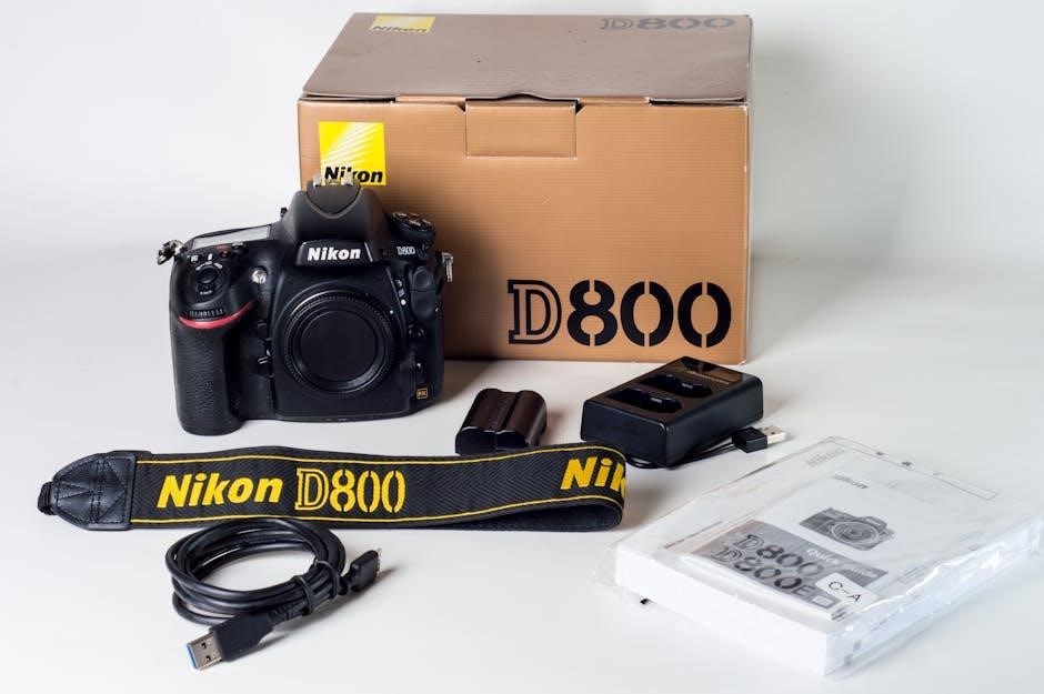
nikon f6 manual

Welcome to the Nikon F6 manual guide‚ designed to help you master this professional-grade film SLR camera. This comprehensive resource covers everything from basic operations to advanced features‚ ensuring you maximize your camera’s potential. Whether you’re a seasoned photographer or a new user‚ this manual provides essential insights to enhance your shooting experience.

Overview of the Nikon F6 Camera

The Nikon F6 is a professional-grade 35mm film SLR camera designed for precision and durability. It features Nikons advanced 11-area autofocus system (Multi-CAM2000) with 9 cross-type sensors‚ ensuring fast and accurate focusing. The camera supports multiple exposure modes‚ including program‚ aperture priority‚ shutter priority‚ and manual control. With its robust build quality and weather-sealing‚ the F6 is ideal for demanding environments. It also offers versatile metering modes‚ including 3D Color Matrix Metering‚ and compatibility with a wide range of Nikkor lenses and accessories‚ such as the MB-40 battery grip. This camera balances tradition with innovation‚ making it a favorite among film photographers seeking reliability and creative control.

Importance of Reading the Manual

Reading the Nikon F6 manual is essential to fully understanding and utilizing the camera’s advanced features. The F6 is a sophisticated film SLR with complex functions‚ and the manual provides detailed explanations to help users navigate its operation. It covers key aspects like autofocus‚ metering modes‚ and custom settings‚ ensuring you avoid errors and optimize performance. By thoroughly reviewing the manual‚ photographers can explore advanced techniques‚ troubleshoot common issues‚ and maintain the camera’s longevity. This guide is indispensable for both novice and experienced users‚ serving as a comprehensive reference to unlock the F6’s full potential and enhance your photographic experience.

Key Features of the Nikon F6

The Nikon F6 boasts exceptional performance with its advanced 11-area autofocus system‚ featuring 9 cross-type sensors for precise focusing. It offers versatile exposure metering modes‚ including 3D Color Matrix Metering‚ ensuring accurate light readings. The camera supports multiple shooting modes‚ such as aperture priority and manual‚ providing creative control. Additionally‚ it is compatible with a wide range of Nikon lenses and accessories‚ including the MB-40 battery grip for extended functionality. These features make the F6 a powerful tool for professional photographers‚ delivering reliability and high-quality results in various shooting conditions.

Nikon F6 Camera Design and Build Quality

The Nikon F6 features a robust titanium alloy body‚ ensuring exceptional durability and weather sealing‚ making it a reliable choice for professional photographers in harsh conditions.

External Controls and Layout

The Nikon F6 features an intuitive and ergonomic design with a titanium alloy body‚ ensuring durability and weather sealing. The camera’s external controls are logically arranged for easy access‚ with a focus on functionality. The top LCD panel displays essential shooting information‚ while the rear LCD provides menu navigation and shooting data. Dual command dials allow for quick adjustments of aperture and shutter speed. The mode button simplifies switching between shooting modes‚ and the focus selector enables precise control over autofocus areas. The optional MB-40 battery grip enhances handling and extends shooting capabilities. This layout ensures efficient operation‚ catering to both professionals and enthusiasts.

Material and Durability

The Nikon F6 is crafted with premium materials‚ featuring a robust titanium alloy body that ensures exceptional durability and lightweight performance. The weather-sealed design protects against moisture and dust‚ making it ideal for challenging environments. The camera’s build quality is meticulous‚ with precise engineering and attention to detail for long-term reliability. The optional MB-40 battery grip further enhances handling and extends shooting capabilities. These features collectively make the F6 a resilient and dependable tool for professionals and enthusiasts alike‚ capable of withstanding rigorous use while maintaining optimal performance in diverse shooting conditions.

Focusing and Metering Systems

The Nikon F6 features the advanced Multi-CAM2000 autofocus system and precise exposure metering modes‚ ensuring sharp focus and accurate light measurement for exceptional image quality consistently.

Autofocus System (Multi-CAM2000)

The Nikon F6 is equipped with the Multi-CAM2000 autofocus system‚ featuring 11 focus areas‚ including 9 cross-type sensors for enhanced accuracy. This advanced system excels in continuous high-speed shooting‚ delivering rapid and precise subject tracking. The cross-type sensors improve performance in various lighting conditions‚ ensuring sharp focus even in challenging situations. The Multi-CAM2000 system is particularly effective for dynamic subjects‚ capturing fleeting moments with ease; With its refined algorithms‚ the F6 autofocus minimizes focus hunting‚ providing smooth and reliable operation. This robust system is a cornerstone of the F6’s professional-grade performance‚ making it ideal for photographers who demand speed and precision in their work.

Manual Focus Operation

The Nikon F6 offers precise manual focus control‚ ideal for photographers who prefer or require exacting focus accuracy. The camera features a high-visibility optical viewing screen with interchangeable focusing screens‚ including type A (plain) and type E (grid lines)‚ to suit various shooting needs. Manual focus is achieved using the lens focus ring‚ with optional electronic focus confirmation available. The system supports smooth‚ intuitive operation‚ allowing photographers to fine-tune focus with ease. Additionally‚ the F6’s ergonomic design‚ including the optional MB-40 battery grip‚ enhances stability for manual focus shooting. This feature is particularly beneficial for genres like macro photography‚ portraiture‚ or when precise control over focus is critical for creative expression.

Exposure Metering Modes

The Nikon F6 offers advanced exposure metering modes‚ including 3D Color Matrix Metering‚ Center-Weighted Metering‚ and Spot Metering. The 3D Color Matrix Metering system uses 11-area sensors and color information for precise exposure calculation‚ adapting to scenes with complex lighting. Center-Weighted Metering prioritizes the central area‚ ideal for portraits‚ while Spot Metering measures a small section for accurate control in challenging conditions. Customization options‚ such as exposure compensation and bracketing‚ allow photographers to fine-tune results. These modes‚ combined with the camera’s intuitive controls‚ provide flexibility and reliability for achieving optimal exposures in various shooting scenarios.

Shooting Modes and Customization

The Nikon F6 offers Program‚ Aperture Priority‚ Shutter Priority‚ and Manual modes‚ providing versatility for photographers. Custom settings enable personalization for enhanced control and tailored shooting experiences.

Program‚ Aperture Priority‚ Shutter Priority‚ and Manual Modes

The Nikon F6 offers four primary shooting modes‚ each tailored for different photography needs. Program Mode (P) automatically adjusts aperture and shutter speed for quick‚ balanced results. Aperture Priority (A) allows users to set the aperture‚ with the camera adjusting the shutter speed accordingly‚ ideal for controlling depth of field. Shutter Priority (S) lets photographers set the shutter speed to freeze or blur motion‚ with the camera adjusting the aperture. Manual Mode (M) provides full control over both aperture and shutter speed‚ offering creative freedom for precise exposures. These modes cater to both novice and advanced photographers‚ ensuring flexibility and adaptability in various shooting scenarios.

Custom Settings and Personalization

The Nikon F6 allows for extensive customization‚ enabling photographers to tailor the camera to their preferences. Custom settings include options for autofocus behavior‚ exposure compensation‚ and flash control‚ providing precise control over shooting parameters. Users can personalize controls such as button assignments and dial operations‚ enhancing workflow efficiency. The camera also supports optional accessories like the MB-40 battery grip‚ which adds extended functionality and ergonomic advantages. These customization options ensure the F6 adapts seamlessly to individual shooting styles‚ making it a versatile tool for both professionals and enthusiasts. By personalizing settings‚ photographers can optimize their workflow and achieve consistent‚ high-quality results in various shooting conditions.

Accessories and Compatibility

The Nikon F6 is compatible with a wide range of accessories‚ including Speedlights‚ Nikkor lenses‚ and the MB-40 battery grip‚ enhancing functionality and flexibility for photographers.

Compatible Lenses and Accessories

The Nikon F6 supports a broad range of Nikkor lenses‚ including AF‚ AF-D‚ and AF-S models‚ ensuring compatibility with Nikon’s legacy and modern optics. Accessories like the MB-40 battery grip enhance handling and extend shooting capabilities‚ while Speedlights and remote controls add versatility. The camera is also compatible with various focusing screens‚ catering to different photographic needs. This extensive compatibility ensures the F6 remains a versatile tool for photographers‚ allowing seamless integration with a wide array of Nikon accessories to meet specific shooting requirements and enhance overall performance.

Optional Components (e.g.‚ MB-40 Battery Grip)

The Nikon F6 can be enhanced with optional components like the MB-40 Battery Grip‚ which improves ergonomics and extends shooting sessions. This grip supports AA batteries as a backup power source‚ ensuring uninterrupted use. Additional accessories include remote shutter releases‚ wireless controllers‚ and Speedlights‚ which expand the camera’s functionality. These components are designed to integrate seamlessly with the F6‚ offering photographers greater flexibility and convenience. Whether for extended shoots or specialized techniques‚ these optional extras allow users to customize their setup to meet specific needs‚ enhancing the overall photography experience with the Nikon F6.

Troubleshooting and Maintenance

Address common issues like exposure errors or focusing problems with detailed solutions. Regularly clean the camera and lenses to maintain performance. Refer to the manual for specific maintenance tips to ensure optimal functionality and longevity of your Nikon F6.

Common Issues and Solutions

Users of the Nikon F6 often encounter issues such as inaccurate exposure metering‚ mirror lock-up errors‚ or viewfinder condensation. For metering inaccuracies‚ ensure the lens is clean and properly attached. If the mirror locks up‚ check the battery level and ensure the camera is in the correct shooting mode. Condensation in the viewfinder can be resolved by allowing the camera to acclimate to ambient temperature. Additionally‚ regular cleaning of the camera and lenses prevents dust buildup‚ which can interfere with autofocus and image quality. Refer to the manual for detailed solutions to these and other common issues.

Cleaning and Maintenance Tips

Regular cleaning and maintenance are essential to ensure the Nikon F6 operates at its best. Use a soft‚ dry cloth to wipe the camera body and external controls‚ avoiding harsh chemicals. For the viewfinder and mirror chamber‚ employ a microfiber cloth or an anti-static brush to remove dust. Clean lenses with a specialized lens tissue or brush‚ avoiding direct contact with the glass. Check for fungi or mold in the mirror chamber and viewfinder regularly‚ especially in humid environments. Store the camera in a dry‚ cool place to prevent condensation. Refer to the manual for detailed instructions on disassembling and cleaning internal components safely.

The Nikon F6 manual serves as an indispensable guide for unlocking the full potential of this exceptional film SLR camera. By following the instructions and tips outlined‚ you can master its advanced features‚ ensuring optimal performance in various shooting conditions. Whether you’re a professional or an enthusiast‚ the F6’s durability‚ precision‚ and compatibility with Nikon’s extensive accessory range make it a timeless choice. Regular maintenance and proper care will extend the life of your camera‚ allowing you to continue capturing stunning images. Keep this manual handy as a reference‚ and enjoy the creative freedom the Nikon F6 offers in your photographic journey.

Byvelma

modine heater manual

Welcome to the Modine Heater Manual; This guide provides essential information for installing‚ operating‚ and maintaining your Modine heater‚ ensuring safety and optimal performance.

1.1 Overview of Modine Heater Products

Modine offers a diverse range of heaters‚ including gas-fired‚ electric‚ and radiant infrared models‚ designed for efficiency and versatility. These products cater to various heating needs‚ from commercial to residential applications. Known for innovative designs‚ Modine heaters provide reliable performance‚ energy efficiency‚ and customizable solutions to suit different spaces and environments.

1.2 Importance of Following the Manual

Following the Modine Heater Manual is crucial for safety‚ compliance‚ and optimal performance. It ensures proper installation‚ operation‚ and maintenance‚ preventing potential hazards and system damage. The manual provides detailed guidelines to meet certifications and standards‚ guaranteeing efficiency and reliability. Adhering to the instructions helps avoid risks‚ prolongs heater lifespan‚ and ensures compliance with environmental and safety regulations.

Installation Guidelines

Proper installation is essential for safe and efficient operation. Follow guidelines for unit location‚ venting‚ and gas connections to ensure compliance with safety standards and optimal performance.

2.1 Key Installation Considerations

Ensure proper installation by following key considerations. Verify unit compatibility with local codes and regulations. Check power supply matches unit requirements. Inspect for damage upon arrival. Ensure correct mounting and leveling. Properly secure the unit to prevent vibration. Follow venting and gas connection guidelines to avoid hazards. Consult local authorities for specific requirements. Adhere to manufacturer’s instructions for safe and efficient operation.

2.2 Unit Location and Mounting Requirements

Mount the Modine heater in a location that ensures optimal performance and safety. Install units at least 7 feet above the floor to prevent damage from moving parts. Ensure the area is well-ventilated and free from flammable materials. Avoid installing near chlorinated or acidic vapors. Secure the unit firmly to prevent vibration. Follow manufacturer guidelines for wall or ceiling mounting to maintain stability and efficiency. Proper placement ensures reliable operation and compliance with safety standards.

2.3 Venting and Gas Connections

Proper venting and gas connections are crucial for safe and efficient operation. Use approved vent materials‚ ensuring correct termination and clearance from combustible materials. Gas connections must be secure‚ with pipe sizes avoiding restrictions. Ensure inlet pressure matches requirements (6-7 W.C. for natural gas‚ 11-14 W.C. for propane). The vent system should allow condensate drainage. Power exhausters‚ if used‚ must be Modine-approved to maintain warranty and safety standards.

Safe Operation and Maintenance

Ensure safe operation by following all safety warnings and performing routine maintenance. Regularly inspect and clean components‚ and address any issues promptly to maintain efficiency and prevent hazards.

3.1 Safety Warnings and Precautions

Always adhere to safety guidelines to prevent accidents. Avoid installing heaters near flammable materials or in areas with corrosive vapors. Ensure proper ventilation to avoid gas leaks and carbon monoxide risks. Keep electrical components dry and avoid overloading circuits. Never touch electrical parts with wet hands or while standing on damp surfaces. Regular inspections are crucial to maintain safety standards and prevent potential hazards. Follow all manufacturer recommendations for safe operation. Proper installation and maintenance by qualified professionals are essential to ensure the heater functions safely and efficiently. Failure to comply with safety precautions can lead to severe injury or property damage. Always refer to the manual for specific safety instructions tailored to your Modine heater model. This will help you identify and mitigate potential risks‚ ensuring a safe and reliable heating experience. By prioritizing safety‚ you can enjoy the benefits of your Modine heater while protecting yourself and your environment. Remember‚ safety should never be compromised when dealing with heating equipment. Stay informed and take all necessary precautions to maintain a safe operating environment.

3.2 Routine Maintenance Tips

Regular maintenance ensures optimal performance and longevity of your Modine heater. Clean or replace air filters monthly to improve airflow and efficiency. Inspect heat exchangers and vents for blockages or damage. Check gas connections for leaks and ensure proper ventilation. Lubricate fan motors annually and replace worn belts. Schedule professional inspections annually to identify and address potential issues early. Keep the unit free from dust and debris to prevent overheating. Always follow the manufacturer’s maintenance schedule to uphold warranty conditions. By maintaining your heater regularly‚ you can enhance its efficiency‚ reduce energy costs‚ and ensure reliable operation during colder months. Proper care also minimizes the risk of unexpected breakdowns‚ providing consistent heating performance. Remember‚ routine maintenance is key to extending the lifespan of your Modine heater. Regular upkeep not only saves money but also ensures your heater operates safely and effectively. Stay proactive with maintenance to enjoy uninterrupted heating comfort. Always refer to your manual for specific maintenance instructions tailored to your model. This will help you perform tasks correctly and safely‚ ensuring your heater continues to perform at its best. Consistent maintenance habits are essential for maximizing the benefits of your Modine heating system. Avoid neglecting routine checks‚ as they are vital for maintaining peak performance and safety standards. Your heater’s longevity and efficiency depend on consistent and thorough maintenance practices. Make it a priority to inspect and service your unit regularly to ensure it runs smoothly throughout the heating season; Regular maintenance also helps in identifying minor issues before they escalate into major repairs‚ saving you time and money in the long run. Always keep your Modine heater well-maintained to enjoy reliable and efficient heating all year round.

Technical Specifications

Explore detailed performance data‚ compatible models‚ and accessories for Modine heaters. Specifications include BTU ratings‚ voltage options‚ and certifications‚ ensuring optimal performance and compliance with safety standards.

4.1 Performance Data and Ratings

Modine heaters offer robust performance with BTU ratings from 30‚000 to 400‚000. They feature high-efficiency designs‚ compatible with natural gas and propane. Ratings include static pressure options‚ motor horsepower‚ and airflow capacities. These specifications ensure optimal heating across various applications‚ from residential to commercial spaces‚ while meeting safety and environmental standards for reliable operation.

4.2 Compatible Models and Accessories

Modine offers a range of compatible models‚ including PD‚ BD‚ and HD series heaters‚ designed for versatility. Accessories like power vented systems‚ controls‚ and nozzles enhance performance. Compatible models cater to diverse heating needs‚ ensuring optimal fit for various spaces. Customizable options and installation kits provide flexibility‚ making Modine heaters adaptable to different environments while maintaining reliability and efficiency.

Troubleshooting Common Issues

Identify and resolve issues like ignition problems or error codes. Check gas supply‚ vent connections‚ and electrical links. Ensure proper maintenance for optimal performance.

5.1 Diagnosing Heater Malfunctions

Identify issues by checking for common problems like ignition failure or error codes. Verify gas supply‚ vent connections‚ and electrical links. Consult the manual’s troubleshooting guide for specific solutions. Ensure proper maintenance and inspect for blockages or damage. Addressing malfunctions promptly prevents further damage and ensures safe‚ efficient operation. Always follow safety guidelines when diagnosing and repairing.

5.2 Resetting and Adjusting Controls

To reset your Modine heater‚ locate the reset button and press it firmly. Adjust controls like gas pressure or ignition settings as needed. Ensure proper ventilation and power supply. Refer to the manual for specific instructions. Always turn off power before making adjustments. Correct settings ensure safe and efficient operation‚ preventing malfunctions and optimizing performance.

Warranty and Customer Support

Modine heaters are backed by a comprehensive warranty. Contact their support at 1-800-828-HEAT (4328) or visit their website for assistance with troubleshooting‚ repairs‚ and warranty claims.

6.1 Understanding Warranty Terms

Modine offers a comprehensive warranty program‚ ensuring coverage for parts and labor. Specific terms vary by product‚ but most include protection against defects in materials and workmanship. The warranty period typically ranges from one to five years‚ depending on the model. Proper installation and maintenance are required to maintain warranty validity. Review the warranty document for detailed terms and conditions.

6.2 Contacting Modine Technical Support

For assistance‚ contact Modine’s dedicated support team at 1-800-828-HEAT (4328). Technical support is available to address installation‚ maintenance‚ and troubleshooting inquiries. Visit their official website for resources‚ manuals‚ and troubleshooting guides. Ensure you have your product model number and serial number ready for efficient service. Modine’s team is committed to providing expert solutions to optimize your heating system’s performance and reliability.

Environmental and Safety Compliance

Modine heaters meet rigorous environmental and safety standards‚ ensuring compliance with certifications like CSA and CEC. They are designed for safe operation in various applications.

7.1 Certifications and Approvals

Modine heaters are certified by the Canadian Standards Association (CSA) and approved by the California Energy Commission (CEC). They comply with environmental and safety standards‚ ensuring operational safety and efficiency in various applications‚ including residential and commercial use.

7.2 Handling Hazardous Materials

When handling hazardous materials related to Modine heaters‚ follow safety guidelines to avoid exposure. Properly dispose of chemicals and wear protective gear. Ensure venting systems are clear of flammable vapors‚ and avoid storing flammable liquids near the unit. Refer to the manual for specific precautions to prevent health risks and environmental contamination.

Downloading the Manual

Access the Modine Heater Manual online by visiting the official Modine website. Digital versions are available for models like PD and HD‚ offering comprehensive guides and troubleshooting tips.

8.1 Accessing Digital Versions

Visit the official Modine website to download digital versions of the manual. Models like PD and HD are available‚ ensuring easy access to installation‚ operation‚ and maintenance instructions. These resources are designed to support optimal use and troubleshooting of your Modine heater‚ providing detailed guides for professionals and users alike.

8.2 Navigating the Manual Online

Navigating the Modine Heater Manual online is straightforward‚ with features like search functions and bookmarks for quick access. Use the table of contents to jump to specific sections‚ such as installation guides or troubleshooting tips. Interactive links and clear menus ensure users can easily find information on models like PD and HD‚ optimizing their experience with the manual.

Specialized Features and Options

Explore Modine’s advanced features‚ including corrosion-resistant models‚ customizable controls‚ and optional accessories. These enhance performance‚ efficiency‚ and adaptability‚ ensuring tailored solutions for diverse heating needs.

9.1 Optional Controls and Upgrades

Modine heaters offer optional controls like ignition controllers and step-down transformers for enhanced functionality. Upgrades such as power vented systems and noise-reducing kits improve efficiency and safety. These upgrades ensure tailored solutions for specific heating needs‚ providing flexibility and reliability.

9.2 Customizing Heater Settings

Modine heaters allow customization of settings for optimal performance. Adjustments include blower speed‚ temperature limits‚ and ignition controls. Refer to the manual for specific instructions on tailoring settings to your space. Customization ensures energy efficiency and comfort while maintaining safety standards. Always follow guidelines to avoid damage or hazards. Proper setup enhances heater reliability and longevity.

This manual provides a comprehensive guide to Modine heaters‚ covering installation‚ operation‚ and maintenance. By following these instructions‚ users can ensure safety‚ efficiency‚ and optimal performance. Always refer to the manual for specific details and troubleshooting tips to maximize heater longevity and functionality.

10.1 Summary of Key Points

This manual provides detailed guidance for Modine heaters‚ emphasizing safety‚ proper installation‚ and routine maintenance. Key points include adhering to safety warnings‚ following installation guidelines‚ and performing regular maintenance to ensure optimal performance. Understanding technical specifications and troubleshooting common issues can enhance heater longevity. Always refer to the manual for specific instructions and contact Modine support for assistance.

10.2 Final Tips for Optimal Heater Performance

  • Always follow Modine’s safety guidelines and installation instructions for reliable operation.
  • Perform routine maintenance‚ such as cleaning filters and checking for wear‚ to ensure efficiency.
  • Ensure proper venting and gas connections to avoid hazards and maintain performance.
  • Monitor heater performance regularly and address issues promptly to prevent malfunctions.
  • Use genuine Modine parts for repairs to guarantee compatibility and longevity.
Byvelma

mpc live 2 manual

The Akai MPC Live II is a standalone, portable music production center with a 7-inch high-resolution touchscreen, 16 velocity-sensitive pads, and built-in monitors for professional-grade sound design and sequencing. Designed for both studio and on-the-go use, it features a rechargeable battery, MIDI and audio connectivity, and seamless integration with MPC software. With firmware updates and a comprehensive user manual, it offers endless creative possibilities for musicians and producers.

1;1 Overview of the MPC Live II

The Akai MPC Live II is a standalone music production center designed for seamless creativity. Featuring a 7-inch high-resolution touchscreen, 16 velocity-sensitive RGB pads, and built-in monitors, it offers professional-grade sound design and sequencing. With a rechargeable lithium-ion battery, it’s portable and perfect for both studio and on-the-go use. The device supports MIDI and audio connectivity, ensuring versatile integration with other gear, while its powerful processing capabilities and comprehensive software features make it a hub for modern music production.

1.2 Key Features of the MPC Live II

The Akai MPC Live II boasts a 7-inch high-resolution multi-touch display, 16 velocity-sensitive RGB pads, and built-in stereo monitors for immersive sound. It features internal synth engines, phono and line-level inputs, and three stereo outputs. The device includes a rechargeable lithium-ion battery for portability, MIDI and audio connectivity, and functions as a control surface for MPC software. Its robust processing power and intuitive interface make it a versatile tool for music production and live performance.

Setting Up the MPC Live II

Unbox and connect your MPC Live II using the included USB cable and power adapter. Follow the quick start guide to register your device and download MPC software for enhanced functionality. Ensure proper power connection and initialize the system for seamless operation.

2.1 Unboxing and Initial Setup

Unbox your MPC Live II, ensuring all components are included: the device, power adapter, USB cable, safety manual, and quick start guide. Carefully inspect for damage. Connect the power adapter, turn on the device, and follow on-screen prompts to complete initial setup. Register your MPC Live II on the Akai website to access software downloads and updates, ensuring optimal performance and functionality from the start.

2.2 Connecting the Device to a Computer

To connect your MPC Live II to a computer, use the provided USB cable. Plug one end into the device’s USB port and the other into your computer. Install the MPC software from the Akai website if not already installed. Enable MIDI connectivity in your DAW and ensure the MPC Live II is recognized as a MIDI device. This setup allows seamless integration for music production and file transfers between the device and your computer.

2.3 Powering the Device

The MPC Live II is powered by an internal, rechargeable lithium-ion battery, offering portability for on-the-go use. To charge, connect the included power adapter to the device’s charging port. The battery provides hours of operation, and charging status is indicated by LED lights. For continuous use, plug the device into a power source using the adapter. The MPC Live II also supports USB power when connected to a computer.

Navigating the MPC Live II Interface

The MPC Live II features a 7-inch high-resolution multi-touch display, allowing intuitive navigation via tapping and swiping. Use the data dial and hardware buttons to adjust settings and scroll through menus seamlessly. The interface is designed for efficient browsing, editing, and accessing features, ensuring a smooth workflow for music production.

3.1 Understanding the Touchscreen Display

The MPC Live II’s 7-inch high-resolution multi-touch display provides intuitive control over its functions. Users can tap, swipe, or pinch to navigate menus, adjust settings, and interact with sequences. The screen offers clear visual feedback, with vibrant colors and sharp graphics. Combined with the hardware controls, it streamlines workflow, allowing for seamless browsing, editing, and creation. The display’s responsiveness enhances the overall production experience.

3.2 Using the Hardware Controls

The MPC Live II features 16 velocity-sensitive RGB pads for drumming and sample triggering. Q-Link controls, including a data dial and buttons, allow precise parameter adjustments. Dedicated transport buttons simplify recording and playback. The hardware layout is ergonomically designed for intuitive navigation, enhancing the tactile experience and streamlining production workflows. These controls provide hands-on creativity, making it easier to shape sounds and sequences directly on the device.

Recording and Editing in the MPC Live II

The MPC Live II allows seamless recording of audio and MIDI, with intuitive editing tools for tracks and samples. Its standalone design enables direct capture and manipulation of sounds, making production efficient and creative. Built-in processing tools further enhance your ability to shape and refine your recordings with precision.

4.1 Recording Audio and MIDI

Recording audio and MIDI on the MPC Live II is straightforward. Use the 16 velocity-sensitive pads for drum patterns or melodic lines, while the touchscreen allows for precise MIDI editing. Audio can be captured via phono or line-level inputs, with real-time monitoring through built-in speakers. The device supports both internal and external storage, ensuring your sessions are saved efficiently. MIDI data can also be imported or exported for further collaboration or production needs, making it a versatile tool for creators.

4.2 Editing Tracks and Samples

Edit tracks and samples with precision using the MPC Live II’s intuitive touchscreen and hardware controls. Slice samples, adjust levels, and apply effects directly on the display. The device supports time-stretching and pitch-shifting, allowing for creative manipulation of audio. With hands-on controls, you can fine-tune your tracks effortlessly, making it a powerful tool for shaping and refining your musical ideas into polished productions.

Sequencing and Workflow

The MPC Live II streamlines music production with intuitive sequencing and workflow tools. Its touchscreen interface allows for efficient track arrangement, MIDI editing, and real-time performance adjustments, enabling seamless creativity and precision in both studio and live settings.

5.1 Creating and Managing Sequences

The MPC Live II simplifies sequence creation with its intuitive touchscreen and Q-Link controls. Users can build and arrange tracks effortlessly, with options to edit MIDI events, adjust timing, and layer sounds. The device also supports real-time recording and step sequencing, making it easy to craft complex beats and melodies. Managing sequences is streamlined, with features like track duplication, scene management, and seamless project organization for efficient workflow.

5.2 Optimizing Your Workflow

Maximize efficiency with the MPC Live II by leveraging its intuitive touchscreen, hardware controls, and project organization features. Use the Q-Link knobs for real-time adjustments, and the touchscreen for quick access to editing and mixing tools. Organize your projects with scenes and track folders, and utilize the MIDI Multi capability in firmware updates to control multiple devices seamlessly, enhancing your creative process and productivity.

Using Built-In Synthesizers

The MPC Live II features powerful built-in synthesizers with multiple engines, offering extensive sound design capabilities. Users can create complex sounds by layering oscillators, filters, and LFOs, and apply effects for unique textures;

6.1 Overview of Synth Engines

The MPC Live II features a robust array of built-in synthesizers, including drum, bass, and lead engines. Each engine offers customizable parameters like waveforms, filters, and LFOs, allowing for deep sound sculpting. Users can layer sounds, assign modulation, and apply effects to create unique textures. The intuitive interface simplifies complex synthesis, making it accessible for both beginners and advanced producers to craft compelling sounds.

6.2 Creating Sounds with the Synthesizers

The MPC Live II’s synthesizers empower users to craft rich, dynamic sounds. Select from various waveforms, shape tones with filters, and add depth with LFOs. Layer sounds, assign modulation, and apply effects to create unique textures. The intuitive touchscreen and hardware controls simplify sound design, allowing real-time tweaking. Users can save custom presets, ensuring their sounds are always accessible for future projects. This flexibility makes the synth engines a powerful tool for creative production.

Effects Processing

The MPC Live II offers robust effects processing with multiple built-in engines, allowing users to enhance their sounds with reverb, delay, distortion, and more for professional-quality mixes.

7.1 Applying Effects to Tracks

The MPC Live II allows seamless application of effects to individual tracks or entire projects. Users can assign reverb, delay, distortion, and other effects directly to tracks using the touchscreen or hardware controls. Effects can be adjusted in real-time, enabling precise tweaking of parameters to achieve the desired sound. The intuitive interface makes it easy to layer and mix effects for professional-grade audio processing.

7.2 Using Effects in Real-Time

The MPC Live II enables real-time effects manipulation, allowing for dynamic sound shaping during performance or production. Use the touchscreen or hardware controls to tweak effect parameters like reverb, delay, or distortion on the fly. This feature enhances live performances and offers instant creative experimentation, giving artists full control over their sound in real-time for unprecedented musical expression and spontaneity.

Connectivity and Integration

The MPC Live II offers extensive connectivity options, including MIDI, audio inputs/outputs, USB, and Bluetooth, enabling seamless integration with other music gear, software, and devices for enhanced production workflows.

8.1 MIDI and Audio Connectivity

The MPC Live II features robust MIDI and audio connectivity, allowing users to interface with external gear. It includes MIDI In/Out ports, three stereo outputs, and phono/line-level inputs. The device supports USB connectivity, enabling direct communication with computers and MPC software. This versatile setup ensures seamless integration with other instruments, synthesizers, and production tools, enhancing workflow and creative possibilities for music production.

8.2 Integrating with Other Gear

The MPC Live II seamlessly integrates with external instruments and production tools. It can control MIDI-compatible devices, allowing for dynamic live performances. Additionally, the USB connection enables easy interfacing with computers and MPC software. This versatility makes it a central hub for both studio and live setups, enhancing your music production workflow and creative possibilities.

Firmware Updates and Maintenance

Regular firmware updates enhance performance and add new features like MIDI Multi capabilities and drum synthesizers. Proper maintenance ensures optimal functionality, including resetting the device when necessary.

9.1 Updating the Firmware

To update the firmware on your Akai MPC Live II, visit the Akai Professional website and download the latest firmware version. Follow the on-screen instructions to install the update, ensuring improved performance and access to new features like MIDI Multi capabilities and enhanced synthesizers. Regular updates are essential for maintaining optimal functionality and unlocking additional creative tools.

9.2 Performing Routine Maintenance

Regularly clean the MPC Live II’s touchscreen and pads with a soft cloth to maintain responsiveness. Organize your files and projects to optimize storage. Back up your data frequently to prevent loss. Ensure the rechargeable battery is charged and stored properly when not in use. Check for dust in ports and connections to maintain optimal performance and extend the device’s longevity.

Troubleshooting Common Issues

Check MIDI connections, restart the device, and ensure firmware is updated. Consult the user manual for solutions to specific errors and optimal performance troubleshooting guidance.

10.1 Resolving Technical Problems

Troubleshooting the MPC Live II involves restarting the device, updating firmware, and checking MIDI/audio connections. Power cycling can resolve many issues. Ensure all cables are securely connected and consult the user manual for specific error solutions. Regular firmware updates often fix bugs and improve functionality, keeping your device operating smoothly for optimal performance and reliability.

10.2 Resetting the Device

Resetting the MPC Live II can be done by holding the Shift button and a Pad while powering on. This performs a factory reset, erasing all user data. Ensure all projects are backed up before proceeding. For a soft reset, restart the device normally without holding any buttons. Always update firmware post-reset for optimal functionality and to restore default settings for a fresh start.

Advanced Features and Tips

The MPC Live II offers advanced features like MIDI Multi, internal drum synthesizers, and Bluetooth connectivity. Utilize these tools to enhance production workflows and explore creative sound design possibilities.

11.1 Using the MPC Live II as a Control Surface

The MPC Live II doubles as a powerful control surface for MPC software, enabling seamless integration with your computer-based workflow. Connect via MIDI or USB to control virtual instruments and DAWs like Ableton Live. Use Q-Link Banks to adjust track volumes and parameters, enhancing your production process. This feature bridges standalone and computer-based music creation, offering flexibility and efficiency for modern producers.

11.2 Mastering Advanced Production Techniques

Maximize your creativity with the MPC Live II by exploring advanced techniques like layering samples, creating complex drum patterns, and utilizing the built-in synthesizers. Leverage the drum synthesizer introduced in firmware 2.9 for unique percussion sounds. Experiment with advanced MIDI editing, multi-effects routing, and automation. These features allow for intricate sound design and dynamic performances, taking your music production to the next level with precision and artistry.

The MPC Live II is a powerful tool for music production, offering unmatched portability and versatility. For further learning, explore the official Akai user manual and firmware updates for enhanced functionality. Additional resources, including tutorials and community forums, are available to help you master advanced techniques and troubleshoot common issues, ensuring you get the most out of your MPC Live II.

12.1 Final Thoughts on the MPC Live II

The MPC Live II is a revolutionary, portable music production powerhouse, combining intuitive design with robust features like a high-resolution touchscreen, velocity-sensitive pads, and built-in monitors. Its standalone functionality, rechargeable battery, and seamless software integration make it ideal for both studio and on-the-go workflows. With regular firmware updates and extensive resources available, the MPC Live II continues to empower musicians and producers to create effortlessly, anywhere.

12.2 Additional Resources for Learning

For deeper understanding, explore the official Akai MPC Live II User Manual and Quick Start Guide, available on Akai’s website. Additional resources include firmware updates, video tutorials, and community forums. The Akai Pro website offers detailed guides, while YouTube channels provide hands-on tutorials. Join forums like Akai Professional for troubleshooting and tips. Download the MPC Live II User Guide in multiple languages for comprehensive learning.

Byvelma

how to rebuild a manual transmission

Preparation for Rebuilding a Manual Transmission

Start by researching the transmission model and gathering a detailed repair manual. Use specific keywords like the model number to find accurate parts and instructions. Plan the rebuild process, ensuring all necessary tools and materials are organized. A clean workspace and a systematic approach will help maintain efficiency and reduce errors during disassembly and reassembly. Understanding the transmission’s components and their functions is crucial for a successful rebuild. Create a checklist of steps and required parts to avoid missing critical components. Consider consulting online forums or repair communities for troubleshooting common issues specific to your transmission model. Organize your tools and workspace to keep track of small parts and ensure everything is easily accessible. Review safety guidelines to handle gears and bearings properly, preventing damage or injury. Finally, mentally prepare for the complexity of the task, as rebuilding a manual transmission requires patience and attention to detail.

1.1 Gathering Necessary Tools and Parts

Before starting the rebuild, ensure you have all the necessary tools and parts. Essential tools include a socket set, wrenches, a hydraulic press, and feeler gauges for measuring clearances. Specialized tools like a bearing puller and Torx sockets may also be required, depending on the transmission model. For parts, gather new bearings, seals, and gaskets, as these are typically replaced during a rebuild. Inspect and replace worn or damaged components such as synchronizers, gear sets, and shafts. Use a detailed parts list from a repair manual or supplier to ensure accuracy. Source parts from reputable suppliers, preferably those that meet OEM specifications. Avoid using universal parts without verifying compatibility. Additionally, gather cleaning supplies like solvent and rags, as well as lubricants for reassembly. Organize all parts and tools in a clean, accessible workspace to streamline the process and avoid delays.

1.2 Understanding Transmission Components and Their Functions

Understanding the components of a manual transmission is essential for a successful rebuild. Key components include gears, bearings, synchronizers, and shafts. Gears transmit power between the engine and wheels, while bearings reduce friction and support moving parts. Synchronizers ensure smooth gear shifts by aligning gear speeds. The input and output shafts connect the transmission to the engine and driveshaft, respectively. Other critical parts include the clutch hub, gear sets, and seals. Each component plays a specific role in transmitting power and controlling gear changes. Familiarize yourself with their interactions to diagnose issues and rebuild effectively. Consulting a repair manual will provide detailed diagrams and descriptions tailored to your transmission model. This knowledge will guide you in identifying worn or damaged parts and selecting the right replacements. Understanding these components is the foundation for a proper rebuild and ensures all parts function harmoniously post-reassembly.

Disassembling the Manual Transmission

Begin by removing the transmission from the vehicle and securing it on a workbench. Use specialized tools to detach the gear shafts and bearings carefully. Proceed methodically to avoid damaging internal components during disassembly.

2.1 Removing the Transmission from the Vehicle

Begin by preparing the workspace and gathering necessary tools. Drain the transmission fluid and disconnect the battery for safety. Jack up the vehicle using jack stands to ensure stability and access. Remove the driveshaft and any connecting components like universal joints or CV axles carefully to avoid damage. Disconnect the transmission from the engine, ensuring all electrical connections and linkages are safely detached. Use a repair manual specific to your car model to locate and remove the bolts securing the transmission to the chassis or transmission tunnel. Lower the transmission slowly and safely, possibly with a hoist or assistance from a friend due to its weight. Once removed, transport the transmission to a sturdy workspace and organize all components to prevent loss or misplacement. Stay patient and organized, consulting tutorials or forums if needed, to manage the complexity and ensure a smooth process.

2.2 Disassembling the Transmission Unit

Once the transmission is removed, begin disassembling it by detaching external components like the shift mechanism and bellhousing. Use a puller to remove the bearing assembly and input shaft seal. Carefully extract the mainshaft and countershaft, ensuring gears remain attached. Remove the reverse gear assembly and synchro rings, taking note of their positions for reassembly. Use a press to remove bearings and seals from the shafts and case. Separate the transmission case halves by gently prying them apart, being cautious not to damage the mating surfaces. Remove the differential and final gear components, followed by the gear sets and their respective shafts. Document each step and organize parts to avoid confusion. Handle components with care to prevent damage, especially bearings and gears, which require precise alignment and fitting during reassembly. Keep all parts clean and stored in a logical order for the rebuild process.

Inspection and Cleaning of Transmission Parts

Inspect all components for wear, damage, or excessive mileage. Replace any damaged or worn-out parts, including bearings, seals, and gear teeth. Clean the transmission case and components using solvents and air compressors to remove dirt and old lubricant. Pay special attention to intricate areas like gear pockets and shaft bearings. Use a wire brush to scrub away stubborn grime and debris. Ensure all parts are thoroughly dried before reassembly. Replace worn synchronizers, seals, and gaskets to prevent future leaks or mechanical failure. Document the condition of each part to ensure proper replacement and alignment during reassembly.

3.1 Inspecting for Wear and Damage

Begin by thoroughly examining each transmission component for signs of wear or damage. Inspect gears for pitting, scoring, or chipped teeth, and check bearings for excessive play or discoloration. Look for worn or damaged synchronizers, as these can cause shifting issues. Examine the transmission case for cracks or damage, and verify that all shafts and splines are in good condition. Use a micrometer or feeler gauges to measure wear on critical surfaces. Replace any parts that show significant wear or damage, as these can lead to premature failure. Pay special attention to seals and gaskets, ensuring they are not cracked or deteriorated. Document each part’s condition to ensure proper replacement and alignment during reassembly. This step is crucial for ensuring the transmission operates smoothly and reliably after rebuilding.

3.2 Cleaning the Transmission Case and Components

Clean the transmission case and all components thoroughly to ensure proper inspection and reassembly. Use a high-pressure solvent or degreaser to remove grease, oil, and debris from the case and parts. Scrub stubborn areas with a stiff brush to eliminate grime buildup. Rinse all components with clean solvent or water, depending on the cleaning solution used. For delicate parts, consider ultrasonic cleaning to avoid damage. Once cleaned, dry the transmission case and components with compressed air or a clean, lint-free cloth. Inspect the surfaces for any remaining residue or contamination. Cleanliness is critical to prevent dirt or old lubricant from affecting the rebuilt transmission’s performance. Ensure all parts are spotless before moving on to reassembly. This step ensures a smooth and reliable operation of the transmission after rebuilding.

Reassembling the Manual Transmission

Reassemble the transmission by following the service manual’s instructions. Install new bearings, seals, and gaskets. Reattach gears, shafts, and other components in the correct order. Use specialized tools like a press for bearings and seals. Ensure all parts are properly aligned and lubricated. Double-check torque specifications for bolts and fasteners. Test the transmission’s operation before reinstalling it in the vehicle to ensure smooth shifting and proper function.

4.1 Installing New Bearings and Seals

Begin by inspecting the bearings and seals for any damage or wear. Clean the housing thoroughly before installing new components. Use a hydraulic press to install bearings, ensuring they are properly seated. Apply even pressure to avoid misalignment. For seals, lubricate the mating surface and gently press them into place using a seal installer or suitable tool. Refer to the service manual for specific torque and installation guidelines. Verify the fitment and alignment of all components to ensure proper operation. Test the bearings for smooth rotation and the seals for any signs of leakage. Proper installation is critical to prevent premature wear and ensure the transmission operates smoothly. Handle all components carefully to avoid damage or contamination.

4;2 Reassembling Gears and Shaft Components

Reassemble the gears and shaft components by following the service manual’s torque specifications and alignment procedures. Clean all parts thoroughly before installation to ensure proper fitment. Apply a thin layer of lubricant to gear teeth and shaft splines to reduce friction and wear. Use a hydraulic press to install gears onto shafts, ensuring they are properly seated and aligned. Verify the keyway alignment between gears and shafts to maintain correct meshing. Secure components with retaining rings or circlips, ensuring they are fully seated. Reinstall synchro rings and hubs, aligning them with the corresponding gears. Tighten all fasteners in the specified order to avoid misalignment. Use a torque wrench to achieve the recommended torque values. Finally, check the gear engagement and shaft rotation for smooth operation and proper alignment. This step is critical for ensuring the transmission operates efficiently and without noise or vibration.

Testing and Reinstalling the Transmission

After reassembly, test the transmission for leaks and proper function. Reinstall it in the vehicle, ensuring all connections are secure. Check fluid levels and test drive to confirm smooth operation.

5.1 Reinstalling the Transmission in the Vehicle

To reinstall the transmission, begin by lifting the vehicle using a jack and securing it with jack stands for safety. Carefully position the transmission under the vehicle, ensuring it aligns with the engine and chassis mounts. Use a transmission jack to stabilize and maneuver the unit into place. Once aligned, bolt the transmission to the engine and chassis, tightening all mounts securely. Reconnect the driveshaft, clutch cable, and any electrical connectors, ensuring proper alignment and tightness. Refill the transmission fluid to the recommended level and double-check all connections for leaks or loose components; Finally, lower the vehicle and test the transmission in a controlled environment before driving. Proper alignment and secure connections are critical for smooth operation and to prevent future damage.

5.2 Testing the Transmission for Proper Function

After reinstalling the transmission, perform a thorough test to ensure it operates smoothly. Start by idling the engine and checking for unusual noises or leaks. Engage each gear methodically, shifting through all gears to verify smooth operation and proper engagement. Pay attention to any grinding or hesitation, which may indicate misaligned gears or faulty synchronizers. Test the clutch pedal for proper disengagement and engagement, ensuring it doesn’t slip or drag. Once satisfied, take the vehicle for a controlled road test, checking acceleration, shifting, and deceleration in various conditions. Monitor the transmission fluid level and condition, adding more if necessary. Address any issues promptly, as early detection prevents further damage. A successful test confirms the rebuild’s accuracy and readiness for daily use.

Byvelma

honeywell t10 thermostat manual

The Honeywell T10 Pro Smart Thermostat is a cutting-edge device designed to enhance home comfort and energy efficiency through smart technology and seamless integration.

1.1 Overview of Features and Benefits

The Honeywell T10 Pro Smart Thermostat offers advanced features like smart alerts for temperature and humidity, customizable scheduling, and energy-saving modes. It supports up to 20 remote sensors, enabling precise comfort control across your home. With HomeKit integration and voice control, it seamlessly integrates into smart home systems. The thermostat also includes a 200-foot sensor range and priority comfort settings for specific rooms, ensuring optimal efficiency and convenience.

1.2 Compatibility and RedLINK Technology

The Honeywell T10 Pro Smart Thermostat is compatible with most HVAC systems and utilizes RedLINK technology for reliable wireless communication. This technology ensures a strong, 200-foot range connection between the thermostat and its sensors. RedLINK also supports up to 20 remote sensors, allowing for precise temperature and humidity monitoring across multiple rooms, enhancing comfort and energy efficiency throughout your home.

Installation Requirements and Precautions

The Honeywell T10 Pro Smart Thermostat requires compatibility checks with your HVAC system, proper wiring, and a J-box adapter. Follow installation instructions carefully to avoid malfunctions.

2.1 Wiring and Compatibility Check

Ensure your HVAC system is compatible with the Honeywell T10 Pro Smart Thermostat. Verify wiring matches the terminal requirements, including the C-wire for power. Use the K terminal for fan and compressor control in conventional or heat pump systems. Check slider tabs for proper R and other terminal settings. Incorrect wiring can lead to malfunctions or damage, so consult the manual or a professional if unsure.

2.2 Mounting Options and Accessories

The Honeywell T10 Pro Smart Thermostat offers versatile mounting options using the UWP system or a standard J-box adapter. Install the thermostat securely on any wall type. Accessories like the decorative cover plate enhance aesthetics, while optional sensors provide advanced comfort control. Ensure proper alignment and leveling during installation for optimal functionality and display accuracy. Follow the manual’s guidelines for a seamless setup experience.

Setting Up the Thermostat

Power on the thermostat, follow on-screen instructions to connect to Wi-Fi, and complete initial setup using the Resideo app for smart functionality and integration.

3.1 Initial Setup and Configuration

Power on the thermostat and follow the on-screen instructions to connect to your Wi-Fi network. Use the Resideo app to complete the setup, configuring preferences like temperature settings, scheduling, and sensor integrations. Ensure all devices are linked properly for seamless smart functionality and energy monitoring. This step ensures your thermostat is ready for advanced features and remote control capabilities.

3.2 Connecting Remote Sensors

To connect remote sensors, ensure they are powered on and within the 200-foot range of the thermostat. Open the Resideo app, select “Devices & Sensors,” and follow the pairing instructions. Each sensor detects temperature, humidity, and occupancy, allowing the thermostat to prioritize comfort in specific rooms. Securely place sensors in desired locations for accurate readings and optimal performance.

Scheduling and Programming

Set customizable schedules with four adjustable periods: Wake, Away, Home, and Sleep. Use the Honeywell Home app or thermostat interface to program preferences and optimize comfort efficiently.

4.1 Creating a Daily Schedule

Creating a daily schedule on the Honeywell T10 Pro Smart Thermostat is straightforward. Use the Honeywell Home app or the thermostat’s interface to set up to four periods per day—Wake, Away, Home, and Sleep. These settings allow you to customize temperature preferences, ensuring optimal comfort and energy efficiency throughout the day. Adjustments can be made easily to match your lifestyle and preferences.

4.2 Adjusting Temperature Setpoints

Adjusting temperature setpoints on the Honeywell T10 Pro Smart Thermostat ensures precise comfort control. Use the Honeywell Home app or the thermostat’s interface to set desired temperatures for heating and cooling. The thermostat offers +/-1F precision, allowing you to customize comfort levels. Temperature adjustments can be made manually or automated through schedules, ensuring energy efficiency and optimal comfort throughout the day.

Smart Alerts and Notifications

The Honeywell T10 Pro Smart Thermostat sends customizable alerts for temperature, humidity, and maintenance reminders, ensuring you stay informed about your home’s comfort and system status.

5.1 Customizable Alerts for Temperature and Humidity

The Honeywell T10 Pro Smart Thermostat offers customizable alerts for temperature and humidity levels, ensuring you’re notified when conditions exceed set thresholds. Receive notifications on your mobile device for extreme temperatures, potential pipe bursts, or high humidity. These alerts help prevent damage and maintain optimal comfort. Set specific ranges for temperature and humidity to tailor notifications to your needs, enhancing energy efficiency and home comfort.

5.2 Maintenance Reminders and Filter Alerts

The Honeywell T10 Pro Smart Thermostat provides maintenance reminders and filter alerts to ensure your HVAC system runs efficiently. Receive notifications when your air filter needs replacement or when system maintenance is required. These alerts help maintain optimal performance, reduce energy bills, and extend equipment lifespan. Customizable settings allow you to schedule reminders based on usage or time, keeping your system in peak condition.

Advanced Features and Settings

Explore advanced features like auto-change mode, priority comfort, and smart alerts. These settings optimize your home’s temperature and energy use, ensuring comfort and efficiency year-round.

6.1 Auto Change Mode for Heating and Cooling

The Honeywell T10 Pro Smart Thermostat features an Auto Change mode that automatically switches between heating and cooling based on the desired temperature. This intelligent feature ensures your home stays comfortable without manual adjustments. It adapts to your schedule and preferences, optimizing energy use while maintaining consistent temperatures. Ideal for climates with varying conditions, it simplifies temperature control and enhances efficiency.

6.2 Priority Comfort in Specific Rooms

The Honeywell T10 Pro Smart Thermostat’s Priority Comfort feature allows setting specific temperatures in different rooms via remote sensors. It averages these to ensure comfort where needed, ideal for large homes with varying requirements. Managed through the Honeywell Home app, it supports up to 20 sensors, enhancing energy efficiency and personalized comfort seamlessly.

Troubleshooting Common Issues

Address common issues like loss of signal, sensor connectivity, or display malfunctions. Check wiring, restart the system, or reset the thermostat to restore functionality effectively.

7.1 Loss of Signal or Sensor Connectivity

If the T10 Pro Smart Thermostat loses connection with remote sensors or RedLINK devices, ensure sensors are within the 200-foot range. Check for physical obstructions, move sensors closer, or restart the system. Verify sensor batteries and wiring. Resetting the thermostat or updating firmware may resolve connectivity issues. Consult the user manual for detailed troubleshooting steps to restore signal stability and functionality.

7.2 Resetting the Thermostat

To reset the Honeywell T10 Pro Smart Thermostat, press and hold the center button for 5 seconds until the screen resets. This clears the current schedule and preferences but retains Wi-Fi settings. For a factory reset, go to the menu, select “Settings,” then “Reset,” and choose “Factory Reset.” This will erase all settings, requiring a full reconfiguration. Refer to the user manual for detailed reset procedures and guidelines.

HomeKit Integration and Compatibility

The Honeywell T10 Pro Smart Thermostat seamlessly integrates with Apple HomeKit, enabling voice control via Siri and smart home system compatibility for enhanced convenience.

8.1 Setting Up HomeKit on the T10 Pro

To set up HomeKit on the Honeywell T10 Pro, access the menu, select HomeKit Setup, and follow the on-screen instructions. Ensure your device is connected to the same Wi-Fi network. Use the Resideo App to complete the integration, enabling voice control via Siri and compatibility with Apple’s smart home ecosystem for a seamless experience.

8.2 Voice Control and Smart Home Integration

The Honeywell T10 Pro supports voice control through Siri and Apple HomeKit, allowing users to adjust settings hands-free. Integration with smart home systems enables seamless control of your thermostat alongside other compatible devices. Use voice commands to change temperatures or schedule settings, enhancing convenience and energy management. This feature ensures a connected and intuitive smart home experience.

Energy Efficiency and Savings

The Honeywell T10 Pro promotes energy efficiency by optimizing temperature settings and tracking usage, helping reduce energy waste and lower utility bills through smart scheduling.

9.1 Optimizing Temperature Settings

The Honeywell T10 Pro Smart Thermostat offers advanced features to optimize temperature settings, ensuring energy efficiency. With smart scheduling and geofencing, the thermostat learns your preferences and adjusts temperatures accordingly. Remote sensors detect conditions in specific rooms, allowing the system to preemptively adjust heating or cooling. This intelligent approach balances comfort and energy savings, reducing unnecessary consumption while maintaining optimal home conditions.

9.2 Tracking Energy Usage

The Honeywell T10 Pro Smart Thermostat allows users to track energy usage through the Resideo App, providing detailed insights into heating and cooling consumption. The app generates reports highlighting energy trends, helping users identify opportunities to reduce waste. By monitoring usage patterns, homeowners can make informed decisions to optimize settings and lower utility bills while maintaining comfort.

This concludes the guide for the Honeywell T10 Pro Smart Thermostat. For further assistance, refer to the full user manual or contact Honeywell’s customer support team.

10.1 Where to Find the Full User Manual

The full user manual for the Honeywell T10 Pro Smart Thermostat can be found on the official Honeywell Home website or through the Resideo website. Visit Honeywell Home or Resideo and search for the T10 Pro model. The manual is available for download in PDF format, providing detailed instructions for installation, setup, and troubleshooting. Refer to page 2 for the table of contents to navigate easily.

10.2 Customer Support and Assistance

Honeywell offers comprehensive customer support for the T10 Pro Smart Thermostat. Visit the official Honeywell Home website for troubleshooting guides, FAQs, and contact options. You can reach support via phone, email, or live chat. Additionally, the Honeywell Home app provides instant answers through AI chat. For detailed assistance, submit a request through the Resideo website or refer to the user guide.

Byvelma

honeywell economizer controller manual

The Honeywell Economizer Controller, specifically the JADE W7220 module, is a advanced HVAC control system designed to optimize energy efficiency by utilizing outdoor air for cooling, reducing mechanical cooling demands, and integrating with sensors and actuators for precise environmental control․

1․1 Overview of the Honeywell Economizer Controller

The Honeywell Economizer Controller, specifically the JADE W7220 module, is a sophisticated system designed to optimize HVAC energy efficiency․ It operates as a standalone unit or integrates with advanced sensors for enhanced functionality․ The module features an LCD display and keypad for user interaction, automatically detecting connected sensors and indicating failures․ It supports optional components like CO2 sensors and damper actuators, enabling precise control of outdoor air usage for free cooling․ This system is expandable, allowing for tailored configurations to meet specific HVAC requirements, ensuring optimal performance and energy savings․

1․2 Importance of Economizer Controllers in HVAC Systems

Economizer controllers play a crucial role in HVAC systems by optimizing energy consumption and reducing operational costs․ They enable systems to use outdoor air for cooling when conditions are favorable, lowering the need for mechanical cooling․ This not only enhances energy efficiency but also improves indoor air quality by introducing fresh air․ Honeywell’s advanced controllers, like the JADE W7220, integrate seamlessly with sensors and actuators, providing precise control and adaptability to varying environmental conditions․ Their ability to automate and regulate airflow ensures consistent comfort while minimizing energy usage, making them essential for modern HVAC applications․

System Components

The Honeywell Economizer Controller system includes the JADE W7220 module, optional CO2 and mixed air sensors, damper actuators for airflow control, and Sylk Bus sensors for advanced monitoring, ensuring efficient HVAC operation and environmental regulation․

2․1 JADE W7220 Economizer Module

The JADE W7220 Economizer Module is the central component of Honeywell’s economizer control system, designed to optimize HVAC efficiency․ It features an LCD display and keypad for user interaction, enabling configuration and monitoring of economizer functions․ The module can operate as a stand-alone controller, directly connected to outdoor air sensors, or integrate with Sylk Bus sensors for advanced functionality․ It automatically detects connected sensors and actuators, ensuring seamless communication and operation․ The W7220 supports both dry-bulb and enthalpy-based economizer strategies, providing flexible solutions for energy-efficient HVAC control;

2․2 Optional Sensors for Enhanced Functionality

Optional sensors, such as CO2, enthalpy, and mixed air temperature sensors, enhance the Honeywell Economizer Controller’s functionality․ These sensors provide precise data on indoor air quality, humidity, and temperature, enabling advanced control strategies like demand control ventilation (DCV)․ The C7232 CO2 sensor and C7400 enthalpy sensor can be integrated via Sylk Bus or analog connections, offering flexibility․ Up to three Sylk Bus sensors can be connected, allowing for differential enthalpy control․ These sensors improve system efficiency and indoor comfort while ensuring compliance with energy-saving strategies․

2․3 Damper Actuators and Their Role

Damper actuators, such as the Honeywell MS3103J and MS7503 models, are essential for controlling outdoor air dampers in HVAC systems․ These actuators directly connect to the W7220 Economizer Module, enabling precise modulation of damper positions to regulate airflow․ They ensure optimal outdoor air intake for free cooling, improving energy efficiency and maintaining indoor air quality․ Available in both direct-coupled and communicating configurations, these actuators provide reliable and accurate control, adapting to system demands for enhanced performance and comfort․

2․4 Sylk Bus Sensors for Advanced Control

Sylk Bus sensors, including the C7400S enthalpy and C7250A temperature sensors, integrate seamlessly with the W7220 module, enhancing control capabilities․ These sensors provide precise measurements of temperature, humidity, and enthalpy, enabling advanced economizer functions like differential enthalpy control․ They communicate directly over the Sylk Bus, simplifying wiring and ensuring reliable data transmission․ Up to three sensors can be connected, allowing for comprehensive monitoring of outdoor and return air conditions, which optimizes economizer performance and energy savings in HVAC systems․

Installation and Setup

The JADE W7220 module requires careful installation, starting with pre-installation checks and mounting in an accessible location․ Wiring involves connecting sensors, actuators, and power sources, ensuring all terminals are securely fastened․ The PCMOD interface tool is essential for configuration, allowing users to set parameters and test the system․ Proper setup ensures optimal performance and integration with HVAC systems, leveraging advanced features like Sylk Bus communication for enhanced control․

3․1 Pre-Installation Requirements

Before installing the Honeywell JADE W7220 Economizer Module, ensure the site meets specific requirements․ The module must be mounted in a dry, cool location, protected from direct sunlight and moisture․ Verify that all necessary components, such as sensors, actuators, and wiring, are available and compatible․ Ensure power supply matches the module’s specifications (24 VAC)․ Familiarize yourself with the installation manual and ensure the PCMOD interface tool is ready for configuration․ Proper preparation ensures a smooth installation process and optimal system performance․ Compliance with local electrical codes is mandatory for safety and functionality․

3․2 Mounting the Economizer Module

The Honeywell JADE W7220 Economizer Module must be mounted securely in a dry, cool location to ensure proper operation․ The module can be installed on a flat surface or in a duct using the provided mounting hardware․ For sheet metal installation, use self-tapping screws, while the duct mounting kit (part number 50053060-001) is required for in-duct applications․ Ensure the module is positioned away from direct sunlight and moisture to prevent damage․ A stable and secure installation is critical for accurate sensor readings and reliable system performance․ Follow all safety guidelines and manufacturer recommendations for optimal results․

3․3 Wiring the System

Wiring the Honeywell JADE W7220 Economizer Module involves connecting sensors, actuators, and power sources․ Begin by wiring the sensors, such as the mixed air and outdoor air temperature sensors, to the module’s designated terminals․ Next, connect the damper actuators, ensuring proper polarity and voltage compatibility․ The module’s terminal blocks accommodate wires of various gauges․ Follow the wiring diagrams provided in the manual for specific connections, such as AUX1, AUX2, and R terminals․ Ensure all connections are secure to prevent loose wires․ Refer to the wiring application examples in the manual for detailed configurations․ Proper wiring ensures reliable system operation and accurate sensor communication․ Use the duct mounting kit (part number 50053060-001) if installing sensors in the duct․ Always follow safety guidelines to avoid electrical hazards․

3․4 Wiring Application Examples

Wiring application examples for the Honeywell JADE W7220 Economizer Module include stand-alone dry-bulb configurations and advanced setups with Sylk Bus sensors․ In a stand-alone configuration, wire the module directly to sensors, actuators, and mechanical cooling controls․ For enthalpy control, connect Sylk Bus sensors to measure outdoor and return air conditions․ The module supports up to three Sylk Bus sensors for enhanced functionality; Examples include wiring the MS3103J or MS3105J actuators for damper control and integrating CO2 or IAQ sensors for demand control ventilation․ These wiring examples provide clear guidance for configuring the system to meet specific economizer requirements․

Configuration and Setup

The Honeywell JADE W7220 Economizer Module features an intuitive interface with an LCD and keypad for easy configuration․ The menu structure allows users to set parameters, enabling economizer functions like dry-bulb or enthalpy control, and integrates with optional sensors for advanced operation․

4․1 Interface Overview

The Honeywell JADE W7220 Economizer Module boasts a user-friendly interface with an LCD display and keypad, simplifying configuration and operation․ The interface allows users to navigate through menus, adjust parameters, and monitor system status․ The LCD provides clear feedback on economizer functionality, including outdoor air temperature, mixed air conditions, and system errors․ The keypad enables easy navigation and parameter adjustments, ensuring seamless control over economizer operations․ This intuitive design facilitates efficient setup and troubleshooting, making it accessible for both experienced technicians and new users․ The interface is central to the module’s functionality, ensuring precise control and monitoring of HVAC systems․

4․2 Menu Structure and Parameter Configuration

The Honeywell JADE W7220 Economizer Module features a hierarchical menu structure for easy navigation and configuration․ Users can access parameters such as temperature setpoints, damper positions, and economizer modes through the LCD interface․ Key parameters include ECON AVAIL (economizing availability) and ECONOMIZING (active outdoor air usage)․ The menu allows customization of thresholds for outdoor air temperature and humidity, enabling precise control over when to engage free cooling․ Parameter adjustments are made using the keypad, with options to fine-tune settings for optimal energy efficiency and system performance․ This intuitive configuration ensures seamless integration with HVAC systems․

4․3 Setting Up Sensors and Actuators

Setting up sensors and actuators on the Honeywell JADE W7220 Economizer Module involves connecting and configuring devices like temperature, humidity, and CO2 sensors, as well as damper actuators․ The module automatically detects connected Sylk Bus sensors, simplifying setup․ Actuators are configured to control damper positions, ensuring proper outdoor air intake and exhaust․ Users can assign specific functions to each sensor and actuator through the menu interface, allowing for tailored system responses․ Proper calibration and testing ensure accurate operation, optimizing energy efficiency and maintaining desired indoor air quality․ This step is crucial for achieving reliable economizer performance․

Operation Modes

The Honeywell JADE W7220 Economizer Module operates in stand-alone dry-bulb or enthalpy control modes, optimizing outdoor air usage for energy efficiency and indoor air quality․

5․1 Stand-Alone Dry-Bulb Economizer Configuration

The stand-alone dry-bulb economizer configuration operates independently, using outdoor air temperature to determine if free cooling is available․ It connects directly to a commercial thermostat and sensors, providing basic economizer functionality without advanced features․ This mode is ideal for simple HVAC systems, optimizing energy savings by reducing mechanical cooling when outdoor conditions allow․ The W7220 module controls dampers and stages of cooling based on temperature thresholds․ While efficient, it does not account for humidity, making it suitable for applications where dry-bulb temperature is the primary control parameter․ This configuration is straightforward and cost-effective for smaller systems․

5․2 Enthalpy Control with Sylk Bus Sensors

Enthalpy control with Sylk Bus sensors enhances economizer functionality by measuring both temperature and humidity, enabling precise control of outdoor and return air․ The W7220 module integrates with Sylk Bus sensors, automatically detecting and configuring up to three sensors for advanced control․ This setup allows for differential enthalpy comparison, optimizing free cooling while maintaining indoor humidity levels․ The system supports demand control ventilation (DCV) and provides real-time feedback, ensuring efficient energy use․ This mode is ideal for applications requiring both temperature and humidity management, offering superior performance compared to dry-bulb configurations․

Maintenance and Troubleshooting

Regularly inspect sensors, clean dampers, and verify wiring connections․ Check for Sylk Bus communication errors and address sensor or actuator malfunctions promptly to ensure optimal performance․

6․1 Routine Maintenance Tasks

Regular maintenance ensures optimal performance of the Honeywell Economizer Controller․ Inspect sensors for cleanliness and accuracy, especially temperature and humidity sensors․ Verify wiring connections and check for wear or damage․ Clean damper blades and actuators to prevent mechanical issues․ Use the W7220’s LCD interface to monitor system status and address any error messages promptly․ Replace faulty components and ensure proper communication on the Sylk Bus․ Schedule routine checks to maintain efficiency and prevent unexpected downtime in HVAC operations․

6․2 Common Issues and Solutions

Common issues with the Honeywell Economizer Controller include sensor communication errors, incorrect damper actuator responses, and wiring faults․ For sensor issues, ensure connections are secure and verify Sylk Bus communication․ If a sensor loses communication, the module will display an error, requiring a reset or replacement․ Damper actuators may malfunction due to improper calibration; use the module’s interface to test actuator operation․ Wiring problems can cause system malfunctions; check terminal connections and ensure proper wiring according to the manual․ Regularly inspect and clean components to prevent operational disruptions․

The Honeywell Economizer Controller offers a comprehensive solution for optimizing HVAC system performance, enhancing energy efficiency, and ensuring reliable operation through advanced control and integration capabilities․

7․1 Summary of Key Features

The Honeywell Economizer Controller, particularly the JADE W7220 module, features an intuitive LCD interface, keypad navigation, and compatibility with optional sensors like mixed air and outdoor air temperature sensors․ It supports both stand-alone dry-bulb economizer configurations and advanced enthalpy control using Sylk Bus sensors․ The module automatically detects connected sensors and provides real-time status updates, ensuring efficient operation․ It also integrates with damper actuators for precise control of outdoor air intake, optimizing energy savings and maintaining indoor air quality․ These features make it a robust solution for HVAC systems aiming to maximize efficiency and reduce energy consumption․

7․2 Benefits of Using Honeywell Economizer Controller

The Honeywell Economizer Controller offers significant energy savings by optimizing outdoor air usage, reducing reliance on mechanical cooling․ It enhances system efficiency through precise temperature and humidity control, ensuring optimal indoor air quality․ The module’s compatibility with various sensors and actuators allows for tailored solutions, while its user-friendly interface simplifies operation․ By automating economizer functions, it minimizes manual intervention and potential errors․ Additionally, the controller’s scalability and advanced features make it a cost-effective and environmentally friendly choice for modern HVAC systems, providing long-term operational and financial benefits․